Secondary ejection mechanism and mold adopting same

A secondary ejection and mold technology, which is applied in the field of molds, can solve the problems of complex overall structure of the secondary ejection mechanism, poor integrity of the secondary ejection mechanism, and high processing and production costs, and achieve a simple and convenient secondary ejection structure. The effect of implementing and reducing processing and production costs

Pending Publication Date: 2019-03-22
SHANGHAI BENXU PRECISION MOLD
View PDF4 Cites 3 Cited by
  • Summary
  • Abstract
  • Description
  • Claims
  • Application Information

AI Technical Summary

Problems solved by technology

[0005] In actual use, the secondary ejection mechanism of the single ejector plate combination has poor integrity, and the pneumatic / hydraulic secondary ejection mechanism needs to rely on pneumatic hydraulic equipment to complete the secondary ejection action, which increases production costs. Therefore, the double ejector plate Combined secondary ejection mechanism is more commonly used
However, the overall structure of the secondary ejection mechanism of the double ejector plate combination in the prior art is complex, and the processing and production costs are relatively high. There are room for improvement in the prior art

Method used


Image

  • Secondary ejection mechanism and mold adopting same
  • Secondary ejection mechanism and mold adopting same
  • Secondary ejection mechanism and mold adopting same

Examples


Embodiment 1

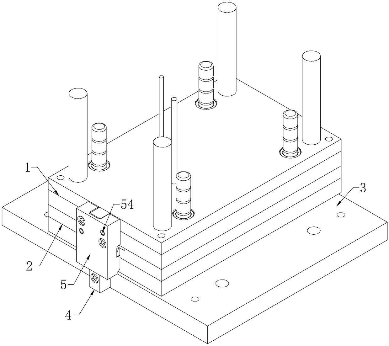
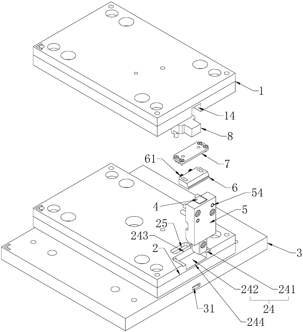
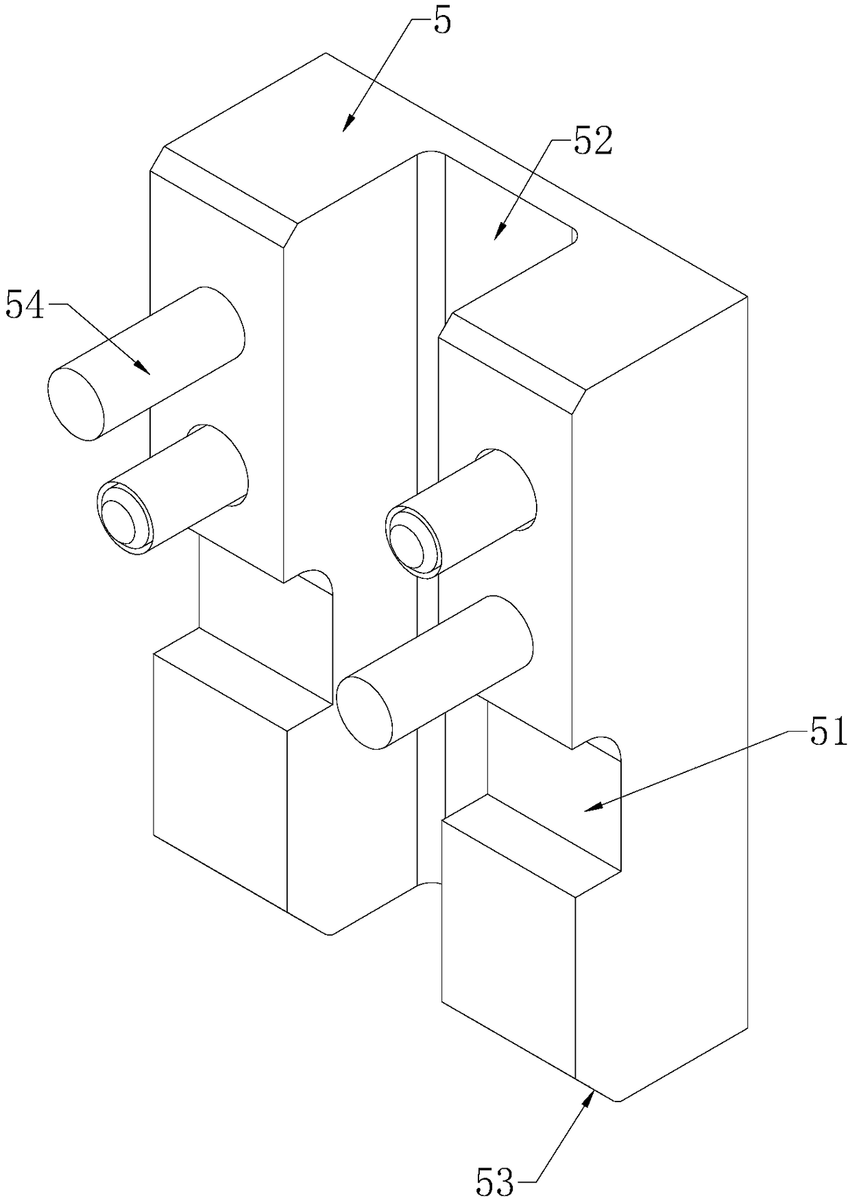
[0044] combine figure 1 and figure 2 As shown, a secondary ejection mechanism includes a guide rod 4 vertically attached to the side of the ejector plate, the bottom end of the guide rod 4 is fixed on the mold bottom plate 3 by screws, and the guide rod 4 slides vertically The shifting sleeve is provided with a fixed cover plate 5, and the fixed cover plate 5 is connected with the upper thimble plate 1 by screws. The lower ejector plate 2 is horizontally provided with a sliding block 6 and an elastic member 61 for driving the sliding block 6 to protrude from the lower ejector plate 2 , and the sliding block 6 partially extends out of the lower ejector plate 2 under the action of the elastic member 61 . On the fixed cover plate 5 and the guide rod 4, limit grooves 51 are respectively offered (referring to image 3 shown) and sliding groove 41 (see Figure 4 shown), and the elastic member 61 drives the sliding block 6 to protrude into the sliding groove 41 and at the same ti...

Embodiment 2

[0055] combine Figure 8 and Figure 9 As shown, a mold includes an upper mold 1A and a lower mold 1B, the top surface of the upper mold 1A and the bottom of the lower mold 1B are provided with a mold base plate 3, and the lower mold 1B and the corresponding mold base plate 3 are arranged There is the secondary ejection mechanism in the first embodiment. The upper ejector plate 1 includes a first ejector plate 11 and a second ejector plate 12 arranged horizontally, and the lower ejector plate 2 includes a third ejector plate 21 and a fourth ejector plate 22 arranged horizontally, and the receiving groove 24 Open at the upper surface of the third ejector plate 21 (combined figure 2 and Figure 9 shown), the mounting groove 14 is opened on the lower surface of the second ejector plate 12 (combined with figure 2 and Figure 9 shown). The four thimble plates are attached to each other in the initial state and can slide vertically along the guide column, and the first thimb...


PUM


Abstract

The invention discloses a secondary ejection mechanism and a mold adopting the same, and relates to the technical field of molds. The mold comprises an upper mold and a lower mold, wherein an ejectorpin plate, an ejector pin and a secondary ejection mechanism are arranged between the lower mold and a mold bottom plate, the secondary ejection mechanism comprises a fixed cover plate connected withan upper ejector plate, and limiting grooves are formed in the fixed cover plate; a sliding block is arranged in the lower layer ejector plate, and an elastic piece is arranged between the sliding block and the lower layer ejector plate; a guide rod penetrates through the fixed cover plate, and the guide rod is fixedly connected with the mold bottom plate, and a sliding groove is formed in the guide rod. The upper ejector plate drives the lower ejector plate to synchronously move, so that one-time ejection operation is achieved; the sliding groove extrudes the sliding block into the lower layer ejector plate, the upper layer ejector plate moves independently, and the secondary ejection action is realized. The secondary ejection structure is simple while the secondary ejection action is achieved, convenient to implement and beneficial to reducing the processing production cost.

Description

technical field [0001] The invention relates to the technical field of molds, in particular to a secondary ejection mechanism and a mold using the secondary ejection mechanism. Background technique [0002] A mold is a cavity tool with a certain shape and size. It is used in conjunction with various internal systems or auxiliary mechanisms to fill various high-temperature liquid materials into the cavity of the mold to produce molds with specific shapes, sizes, and functions. and quality industrial parts. [0003] In general, when the finished product is taken out of the mold, no matter whether a single ejector mechanism or a multi-component ejector mechanism is used, the ejection action is completed at one time. However, due to the special shape of the finished product, or due to the requirements of mass production, if the finished product is still in the mold cavity after one ejection and cannot fall off automatically, it is necessary to add another ejection action. This ...

Claims


Application Information

Patent Timeline
Patent Type & Authority Applications(China)
IPC IPC(8): B29C33/44
CPCB29C33/44
Inventor 戴旭光姜峰
Owner SHANGHAI BENXU PRECISION MOLD
Why Eureka
Try Eureka