
Feeding and discharging system of injection molding machine

A technology for injection molding machines and plastic parts, applied in the field of loading and unloading systems, can solve problems such as unsatisfactory work efficiency, complex control systems, and large space occupation, and achieve convenient and reliable loading and unloading, high system integration, and reduced floor space. Effect

Active Publication Date: 2019-03-22
珠海市欧科锐智能装备有限公司
View PDF5 Cites 7 Cited by
  • Summary
  • Abstract
  • Description
  • Claims
  • Application Information

AI Technical Summary

Problems solved by technology

Due to the different shapes of metal connecting pieces, semi-finished plastic parts and finished plastic parts, most of the injection molding industry uses manual loading, resulting in high labor costs, low work efficiency, high labor intensity, and prone to work-related injuries.
[0003] For this reason, some enterprises have designed manipulators for loading materials, but most of the existing injection molding machines use multiple manipulators to hold different workpieces for feeding, because the shapes of metal connecting pieces, semi-finished plastic parts and finished plastic parts are different. , which makes it difficult for the same manipulator to hold different types of workpieces for feeding at the same time. Only multiple sets of manipulators can be used to hold different workpieces for feeding. Such a design often leads to a large space occupation and the entire cost investment. The loading and unloading position space is limited, resulting in multiple manipulators having to move in sequence, and the overall work efficiency is still unsatisfactory.
Moreover, in the process of unloading after the manipulator clamps the finished plastic parts, generally the existing palletizing devices are in a fixed position. In order to ensure that the finished plastic parts can be arranged in a certain order, only by controlling the unloading manipulator to continuously Adjusting one's own feeding position to adapt to the requirements of the plate placement requires adjustment of the control system of the entire feeding manipulator, so that the feeding position of the finished plastic parts can be arranged in an orderly manner, which is convenient for later identification and use by other equipment. Obviously it will complicate the whole control system

Method used


Image

  • Feeding and discharging system of injection molding machine
  • Feeding and discharging system of injection molding machine
  • Feeding and discharging system of injection molding machine

Examples


Embodiment Construction

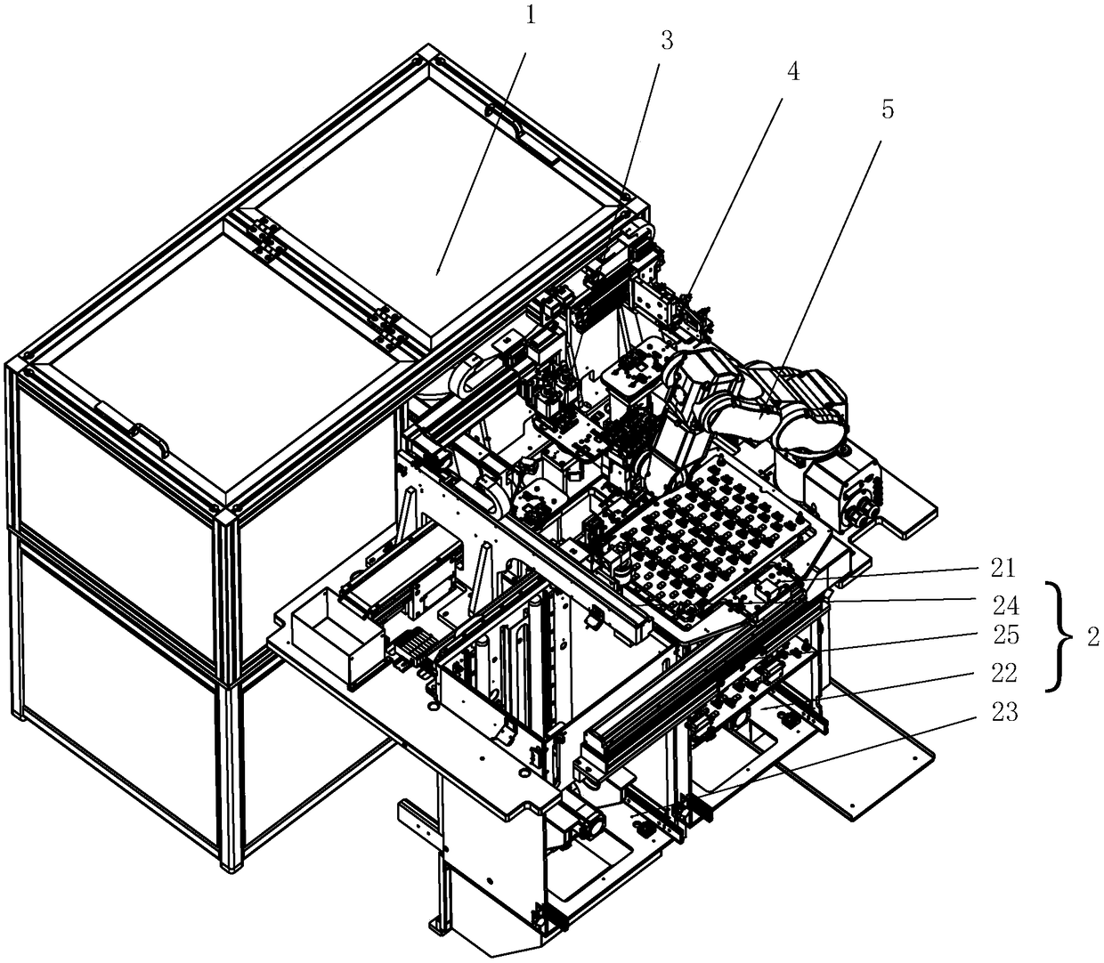
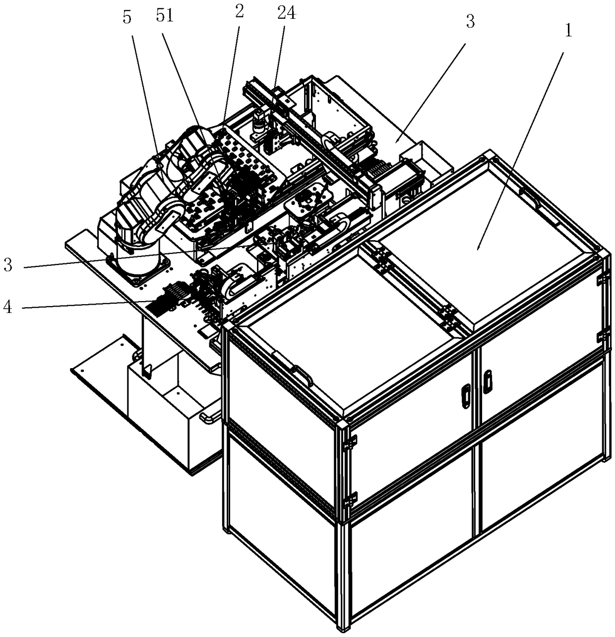
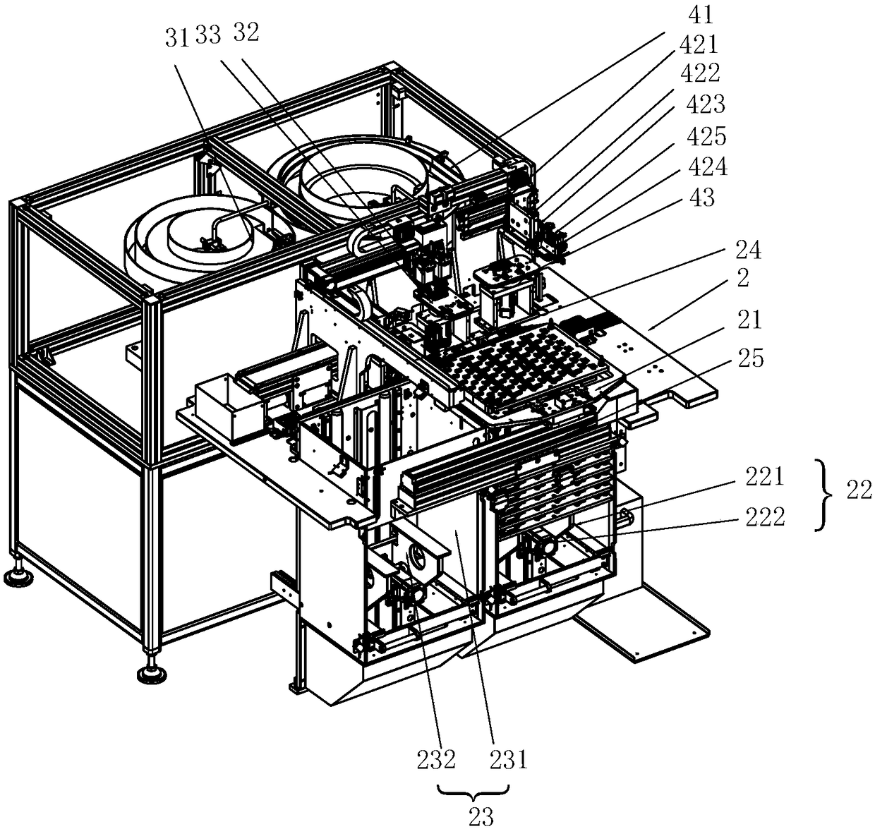
[0029] see Figure 1 to Figure 10, a loading and unloading system of an injection molding machine according to the present invention. The loading and unloading system in this application is installed on the side of the injection molding machine for loading and unloading, and is used to cooperate with the injection molding machine for loading and unloading. The loading and unloading system of this application is provided with a frame 1, and the frame 1 is provided with a receiving device 2 for receiving finished plastic parts, a sheet conveying device 3 for conveying metal connecting sheets, and a feeding device 4 for conveying semi-finished plastic parts And manipulator 5, described manipulator 5 is provided with some clamping stations that can respectively clamp metal connecting piece, semi-finished plastic parts and finished plastic parts, and different clamping stations on described manipulator 5 can correspondingly clamp metal successively. The connecting pieces and semi-f...


PUM


Abstract

The invention discloses a feeding and discharging system of an injection molding machine. The system comprises a machine frame, the machine frame is provided with a receiving device used for receivingfinished plastic parts, a sheet conveying device used for conveying metal connection sheets, a conveying device used for conveying semi-finished plastic parts and a mechanical hand, the mechanical hand is provided with a plurality of clamping stations capable of clamping the metal connection sheets, the semi-finished plastic parts and the finished plastic parts correspondingly, the different clamping stations on the mechanical hand can sequentially and correspondingly clamp the metal connection sheets and the semi-finished plastic parts to be fed into the injection molding machine, the injection-molded finished plastic parts can be taken out and transferred to the receiving device, the receiving device is provided with a transfer set capable of carrying empty trays and gradually transferring the empty trays, and the transfer set can adjust empty positions on the empty trays to receive the finished plastic parts when the mechanical hand places the finished plastic parts to the empty trays. By means of the feeding and discharging system, multi-workpiece simultaneous taking and placing are effectively achieved, the complexity degree of the feeding and discharging system is reduced, and the feeding and discharging efficiency is improved.

Description

technical field [0001] The invention relates to the technical field of injection molding equipment, in particular to a loading and unloading system. Background technique [0002] At present, automotive sensors generally form semi-finished plastic parts first, and then combine them with metal connecting pieces through secondary injection molding to obtain the final product. Due to the different shapes of metal connectors, semi-finished plastic parts and finished plastic parts, most of the injection molding industry uses manual loading, resulting in high labor costs, low work efficiency, high labor intensity, and prone to work-related injuries. [0003] For this reason, some enterprises have designed manipulators for loading materials, but most of the existing injection molding machines use multiple manipulators to hold different workpieces for feeding, because the shapes of metal connecting pieces, semi-finished plastic parts and finished plastic parts are different. , which...

Claims


Application Information

Patent Timeline
Patent Type & Authority Applications(China)
IPC IPC(8): B29C45/14B29C45/17B29C45/42B29C45/38
CPCB29C45/14008B29C45/1769B29C45/382B29C45/42B29C2045/177
Inventor 陈闯
Owner 珠海市欧科锐智能装备有限公司
Learn More