ROV pump type axial flow thruster and multifunctional remote control life buoy thereof

A propeller and life buoy technology, which is applied in the field of ROV pump axial flow propeller and its multifunctional remote control life buoy, can solve the problems of lack of power function of the life buoy, and achieve the effect of improving rescue efficiency

Pending Publication Date: 2019-03-22
QINGDAO HAISHI NETWORK TECH
View PDF8 Cites 6 Cited by
  • Summary
  • Abstract
  • Description
  • Claims
  • Application Information

AI Technical Summary

Problems solved by technology

[0007] In order to solve the problem of lack of power function in existing buoys, the invention discloses an ROV pump type axial flow propeller, which includes a propeller housing, a drive motor, a propeller, a first flap, a second flap and a flap drive mechanism , the front end of the propeller shell is provided with a first water outlet, and the two sides of the rear end are respectively provided with a first water inlet and a second water inlet, the drive motor and the propeller are arranged at the first water outlet, and the two drive connected, the first flap is arranged at the first water inlet, the second flap is arranged at the second water inlet, the flap driving mechanism is arranged on the outer wall of the propeller housing and is connected with the first flap and the The second flap drive connection

Method used


Image

  • ROV pump type axial flow thruster and multifunctional remote control life buoy thereof
  • ROV pump type axial flow thruster and multifunctional remote control life buoy thereof
  • ROV pump type axial flow thruster and multifunctional remote control life buoy thereof

Examples


Embodiment 1

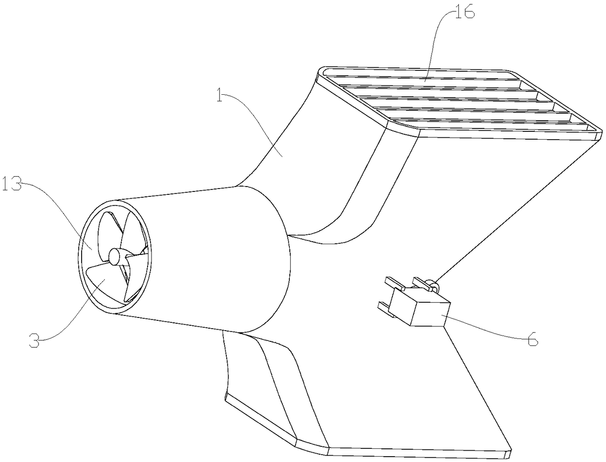
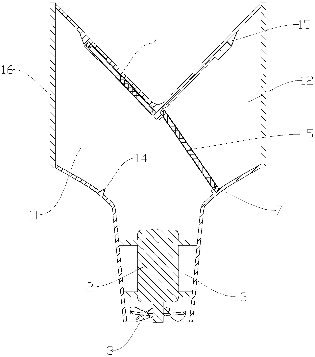
[0037] Such as Figure 1-3 As shown, the ROV pump axial flow propeller of this embodiment includes a propeller housing 1 , a drive motor 2 , a propeller 3 , a first flap 4 , a second flap 5 and a flap driving mechanism 6 .

[0038] The front end of the propeller housing 1 is provided with a first water outlet 13, and the two sides of the rear end are respectively provided with a first water inlet 11 and a second water inlet 12. The drive motor 2 and the propeller 3 are arranged at the first water outlet 13, and the two or transmission connection.

[0039] The driving motor 2 drives the propeller 3 to rotate at a high speed, sucks water from the first water inlet 11 or the second water inlet 12, and pumps it out from the first water outlet 13, thereby generating thrust.

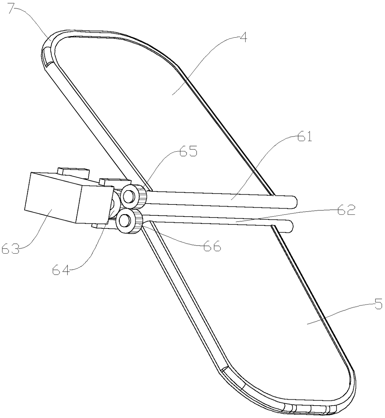
[0040] The first turning plate 4 is arranged at the first water inlet 11, the second turning plate 5 is arranged at the second water inlet 12, and the turning plate driving mechanism 6 is arranged on the oute...

Embodiment 2

[0049] Such as Figure 4-6 As shown, the multifunctional remote control lifebuoy of this embodiment includes a lifebuoy body 10 , a power cabin 20 , a main control unit 30 , a remote controller 40 and a power supply 50 .

[0050] The power cabin 20 is arranged at both ends of the tail of the life buoy body 10, and the ROV pump type axial flow propeller is arranged in the power cabin 20; the upper and lower ends of the power cabin 20 are respectively provided with a third water inlet 21 and a fourth water inlet 22, and the rear end A second water outlet 23 is provided, the first water inlet 11 communicates with the third water inlet 21 , the second water inlet 12 communicates with the fourth water inlet 22 , and the first water outlet 13 communicates with the second water outlet 23 .

[0051] Both the main control unit 30 and the power supply 50 are arranged in the lifebuoy body 10, and the remote controller 40 is connected with the main control unit 30 through wireless signals...


PUM


Abstract

The invention discloses an ROV pump type axial flow thruster, which comprises a propeller shell, a driving motor, a propeller, a first turning plate, a second turning plate and a turning plate drivingmechanism, wherein the front end of the thruster shell is provided with a first water outlet, two sides of the rear end of the thruster shell are respectively provided with a first water inlet and asecond water inlet, the driving motor and the propeller are arranged at the first water outlet and are in transmission connection with each other, the first turning plate is arranged at the first water inlet, the second turning plate is arranged at the second water inlet, and the turning plate driving mechanism is arranged on the outer wall of the thruster shell and is in transmission connection with the first turning plate and the second turning plate. The invention further discloses a multifunctional remote control life buoy comprising the ROV pump type axial flow thruster, wherein the multifunctional remote control life buoy is remotely controlled by arranging the ROV pump type axial flow thruster and a remote controller, the life buoy can quickly and accurately move to a drowning person, and the drowning person does not need to consume physical power to look for the life buoy, and the rescue efficiency is greatly improved.

Description

technical field [0001] The invention relates to the field of lifesaving equipment, in particular to an ROV pump type axial flow propeller and a multifunctional remote control lifebuoy ring. Background technique [0002] The lifebuoy is one of the commonly used water lifesaving equipment, usually made of foam plastic or other light materials with small specific gravity. There are still the following problems in the current life buoy: [0003] 1. During the rescue process, the lifebuoy needs to be thrown manually. If the scene environment is complex and not conducive to rescue, it will greatly affect the rescue work, and even the rescue cannot be carried out smoothly. On the other hand, the existing life buoys are generally thick and heavy, and those with light weight are easily affected by wind force or air resistance, which makes it extremely difficult to control the accuracy of life buoy throwing. Even if the person who falls into the water can catch the lifebuoy, he will...

Claims


Application Information

Patent Timeline
Patent Type & Authority Applications(China)
IPC IPC(8): B63H11/08B63H21/17B63C9/13B63C9/20
CPCB63C9/13B63C9/20B63H11/08B63H21/17B63H2011/081
Inventor 陈敬佩张方超范成叶肖悦魏巍冯凌翔姜雨函
Owner QINGDAO HAISHI NETWORK TECH
Why Eureka
Try Eureka