Transmission structure of micro three-bearing vector spray tube and control method of transmission structure

A technology of vector nozzle and transmission structure, which is applied in the direction of machine/engine, jet propulsion device, etc., can solve the problems such as the inability to solve the problem of lightweight vector nozzle, increase the weight of axisymmetric vector nozzle, and reduce the safety of UAV. , to simplify the complex action of rotational deformation, avoid heavy weight, and achieve the effect of light weight

Active Publication Date: 2019-03-22
CHINA UNIV OF MINING & TECH
View PDF3 Cites 6 Cited by
  • Summary
  • Abstract
  • Description
  • Claims
  • Application Information

AI Technical Summary

Problems solved by technology

At present, the vertical take-off and landing of fixed-wing drones is usually carried out by means of rotating motors, but this exposed propeller greatly reduces the safety of the drone; there is also an axisymmetric vector nozzle similar to the American F35 fighter jet structure, that is, adding a driving gear and a driven ring gear structure at each joint of the axisymmetric vectoring nozzle, and controlling the rotation of the driving gear to drive the driven ring gear to rotate to realize the change of the spraying direction of the vectoring nozzle, but due to the driving motor , the setting of the driving gear and the driven ring gear greatly increases the weight of the axisymmetric vector nozzle, and cannot solve the lightweight problem of the vector nozzle, so the existing fixed-wing UAVs that adopt the structure of the axisymmetric vector nozzle usually Battery life is greatly reduced

Method used


Image

  • Transmission structure of micro three-bearing vector spray tube and control method of transmission structure
  • Transmission structure of micro three-bearing vector spray tube and control method of transmission structure
  • Transmission structure of micro three-bearing vector spray tube and control method of transmission structure

Examples


Embodiment Construction

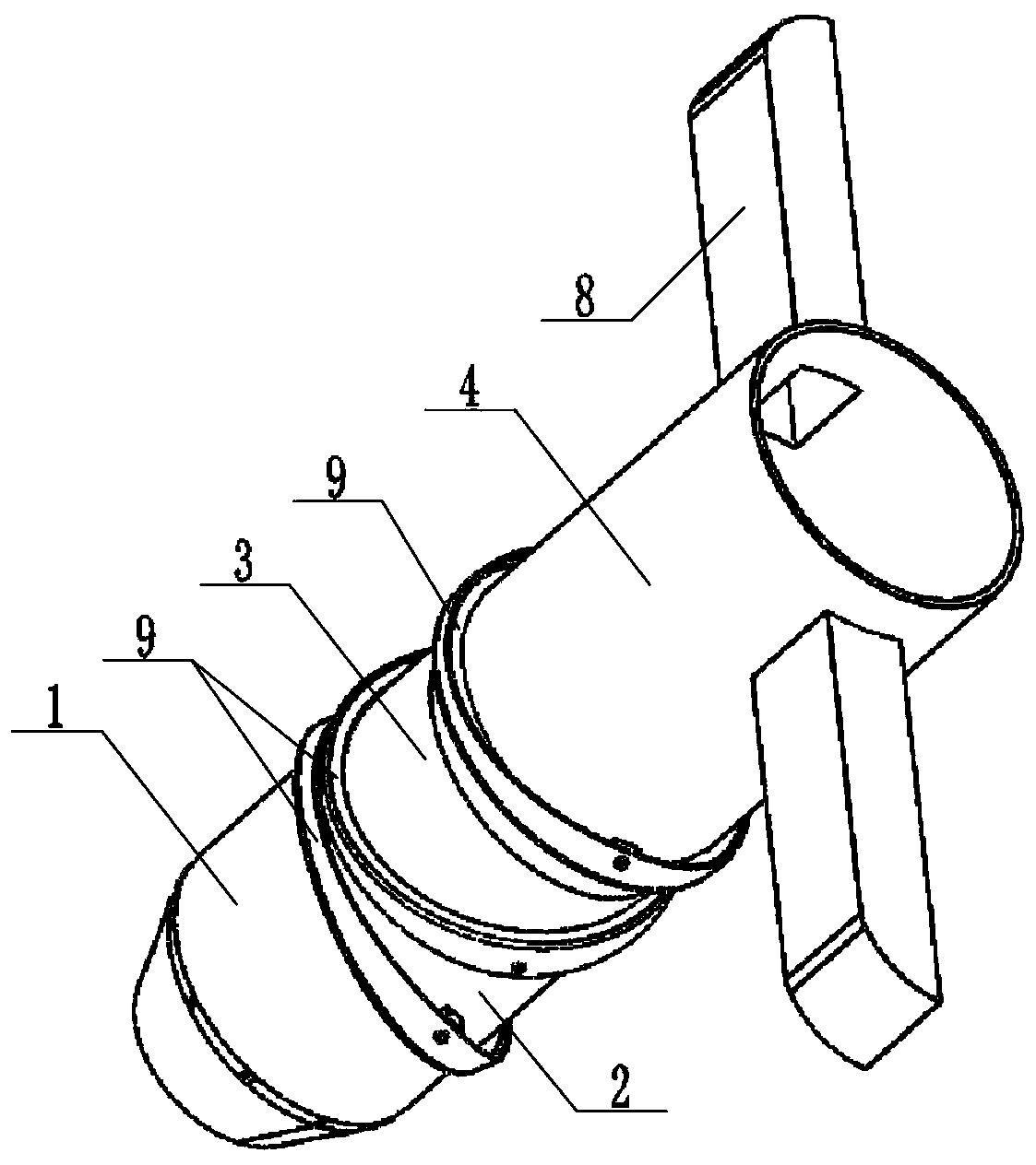
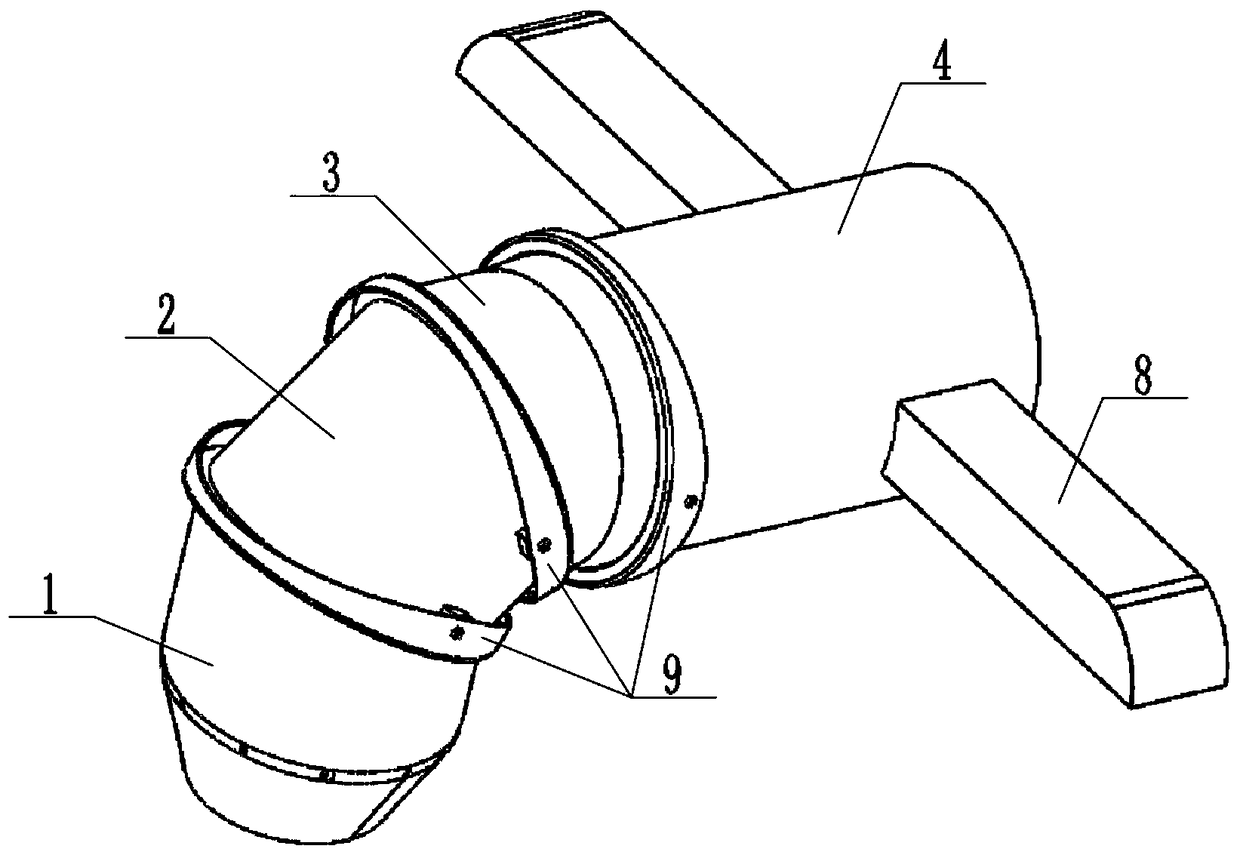
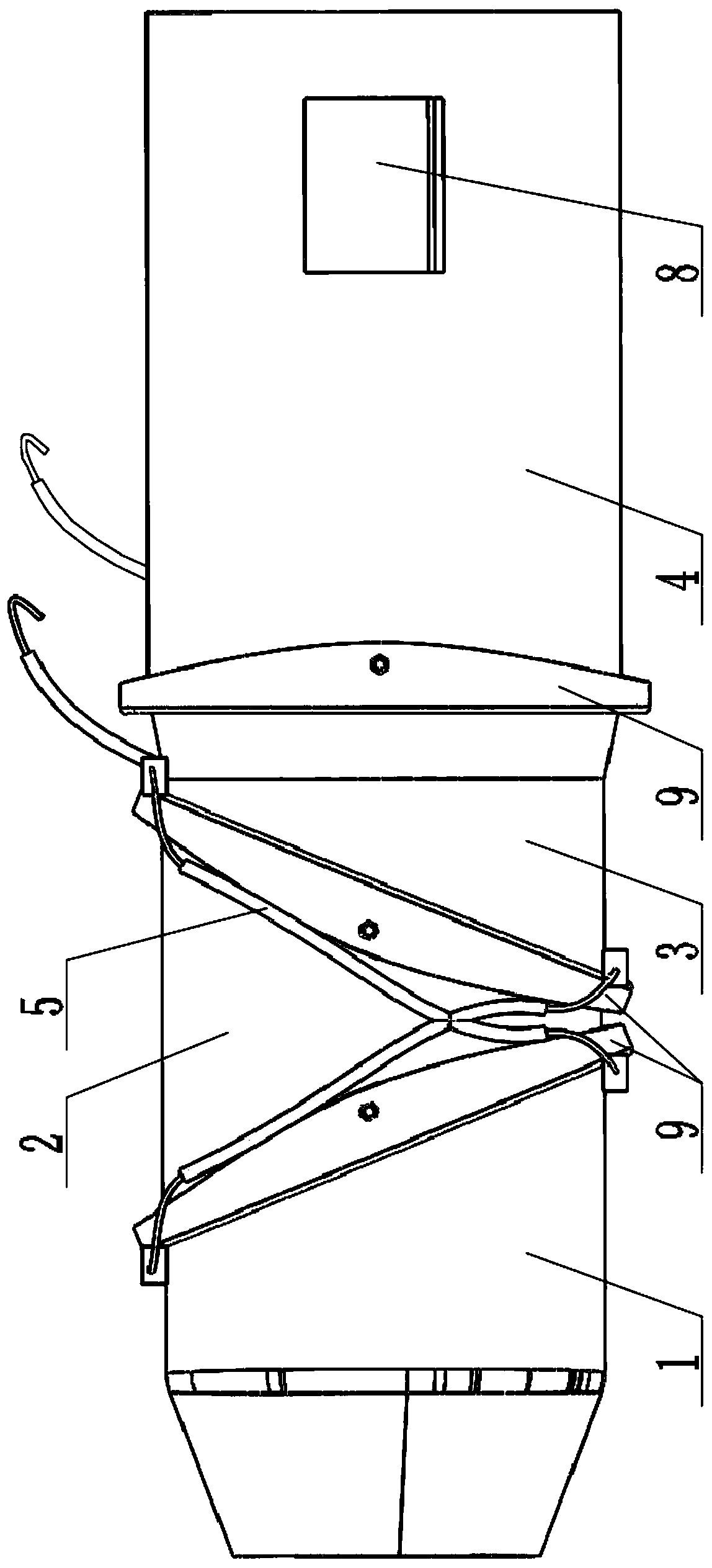
[0027] Below in conjunction with accompanying drawing, the present invention will be further described (hereinafter referred to as figure 1 The left direction of the left direction is the front for description, and the end of the obtuse angle between the inclined plane structure on the nozzle front section 1, the nozzle middle section 2 and the nozzle rear section 3 in the side view direction and the pipe wall is the top of the inclined plane structure For description, the bottom end of the slope structure is described with the end of the slope structure on the front section 1 of the nozzle, the middle section 2 of the nozzle, and the rear section 3 of the nozzle in the side view direction and the angle between the pipe wall and the pipe wall being an acute angle).

[0028] Such as Figure 1 to Figure 4 As shown, the transmission structure of the miniature three-bearing vector nozzle includes an axisymmetric vector nozzle and a vector nozzle traction control mechanism.

[002...


PUM


Abstract

The invention discloses a transmission structure of a micro three-bearing vector spray tube and a control method of the transmission structure. The transmission structure comprises an axisymmetric spray tube and a vector spray tube traction control mechanism, wherein the axisymmetric spray tube comprises a spray tube front section, a spray tube middle section, a spray tube rear section and a spraytube tail section; and the vector spray tube traction control mechanism comprises a spray tube front-rear section traction connecting mechanism, a spray tube middle section traction mechanism and a spray tube tail section traction mechanism. The transmission structure adopts a wire traction way, and a traction part can be fixedly mounted on a machine body of a fixed-wing unmanned aerial vehicle,so that manufacturing complexity degree of the axisymmetric spray tube is greatly reduced, light weight can be realized, power consumption can be reduced, and rotary deformation complex action of theaxisymmetric spray tube can be greatly simplified, and therefore, practicability of a micro vector spray hole becomes possible, the problem that flying range of the fixed-wing unmanned aerial vehicleis relatively short as battery capacity is constant, and the problem that flying requirements of the fixed-wing unmanned aerial vehicle are relatively high are solved.

Description

technical field [0001] The invention relates to a transmission structure and a control method thereof, in particular to a transmission structure and a control method of a miniature three-bearing vector nozzle for a fixed-wing unmanned aerial vehicle, and belongs to the technical field of the fixed-wing unmanned aerial vehicle. Background technique [0002] Unmanned aircraft, referred to as "UAV", is an unmanned aircraft that is controlled by radio remote control equipment and its own program control device, or is completely or intermittently operated autonomously by an on-board computer. UAVs can be divided into military and civilian uses according to their uses. In terms of civilian use, UAVs are currently widely used in aerial photography, agriculture, micro selfies, express delivery, disaster relief, surveying and mapping, news reports, power inspections, disaster relief, film and television shooting, etc. , greatly expanding the use of the drone itself. [0003] UAVs ca...

Claims


Application Information

Patent Timeline
Patent Type & Authority Applications(China)
IPC IPC(8): F02K1/78F02K1/00
CPCF02K1/008F02K1/78
Inventor 李庆华蔡承政高峰杨玉贵张志镇
Owner CHINA UNIV OF MINING & TECH
Why Eureka
Try Eureka