
Backhoe type blade micro-lift pump device

A head pump and vane technology, which is applied to pump devices, parts of pumping devices for elastic fluids, non-variable pumps, etc., can solve the problem of unstable unit operation, low efficiency of pump devices, and low pressure on the suction surface of blades and other issues, to achieve the effect of urban pollution prevention and control, major economic benefits, and important academic significance

Pending Publication Date: 2019-03-22
YANGZHOU UNIV
View PDF0 Cites 0 Cited by
  • Summary
  • Abstract
  • Description
  • Claims
  • Application Information

AI Technical Summary

Problems solved by technology

[0005] The purpose of the present invention is to solve the problem that the water inlet and outlet channels of the existing low-lift pumps are all closed structures, the structure of the pump device is complex, the hydraulic loss is relatively large, the pressure on the suction surface of the blade is low, cavitation is easy to occur, the efficiency of the pump device is low, and the operation of the unit is not good. In order to overcome the shortcomings of stability and other defects, a backhoe blade micro-lift pump device is proposed, which optimizes the structure of the micro-lift pump device, which can improve the performance of the pump under extremely low-lift conditions, and can realize both waterlogging in low-lying areas and low-lift irrigation , it can also be used as a running water appliance to realize urban anti-pollution and pollution control, which has important academic significance and great economic benefits

Method used


Image

  • Backhoe type blade micro-lift pump device
  • Backhoe type blade micro-lift pump device
  • Backhoe type blade micro-lift pump device

Examples


Embodiment Construction

[0020] The present invention will be further described below in conjunction with accompanying drawing:

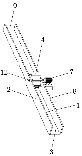
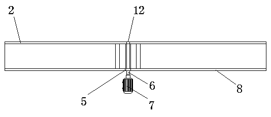
[0021] like Figure 1-5 As shown, a backhoe vane micro-lift pump device includes a motor 7 and a pump shaft 6 connected to the output shaft of the motor 7; the micro-lift pump device is also composed of a base plate 1, a left slot plate 2, a right slot plate 8 and an impeller 4 components; the left trough 2 and the right trough 8 are respectively fixed on the left and right sides of the bottom plate 1, and the left trough 2 and the right trough 8 respectively form a whole with the bottom plate 1. The front end is the water inlet 3 and the rear end is the water outlet 9. type water tank, the groove bottom surface of the water outlet groove 9 is higher than the groove bottom surface of the water inlet groove 3, and an arc transition connection is formed between the water outlet groove 9 and the water inlet groove 3, and the impeller 4 is arranged at the arc transition connect...


PUM


Abstract

The invention discloses a backhoe type blade micro-lift pump device, and belongs to the technical field of hydraulic engineering machinery. The backhoe type blade micro-lift pump device is structurally formed by connecting a bottom plate, a left trough plate, a right trough plate, an impeller, a motor and pump shaft components. The structure is novel, conventional straight plate type blades are changed into backhoe type blades, and a hub ratio and the installation method of the blades are changed. Original unstable power such as water flow and wind power is changed to stable power provided bythe motor, so that the backhoe type blade micro-lift pump device is able to be stably operated at a lift of 0-2 meters. The number of the blades of the device and the hub ratio can be adjusted according to the actual engineering changes. The impeller is in the form of a drum, the device has no rim, water and air can be in direct contact, a free fluid surface exists, no negative pressure occurs during operation, and no cavitation occurs, so that the pump performance during the operation under extremely low lift working conditions is improved, drainage in low-lying areas and low lift irrigationcan be achieved, and the backhoe type blade micro-lift pump device can further be used as a flowing water device to achieve urban anti-pollution and pollution control and has important academic significance and significant economic benefits.

Description

technical field [0001] The invention belongs to the technical field of water conservancy engineering machinery, and relates to a head pump device, in particular to a backhoe-type blade micro-lift pump device. Background technique [0002] A water pump is a machine that converts and transmits energy. The power machine drives the water pump to run, and the mechanical energy of the power machine is converted into the kinetic energy and potential energy of the water through the water pump, that is, the energy of the power machine is transferred to the water to achieve the purpose of lifting water and increasing water pressure. Therefore, the water pump is also a kind of water lifting machine. Water pumps are widely used in agricultural irrigation and drainage, for agricultural production and disaster reduction and prevention services, and are also widely used in industrial enterprises and urban construction, serving industrial production, urban construction, flood control and d...

Claims


Application Information

Patent Timeline
Patent Type & Authority Applications(China)
IPC IPC(8): F04D13/06F04D29/24F04D29/66
CPCF04D13/06F04D29/24F04D29/669
Inventor 汤方平张文鹏石丽建陈晔
Owner YANGZHOU UNIV
Learn More