
Core barrel sealing structure capable of increasing sealing specific pressure

A technology of sealing structure and core barrel, which is applied to the extraction of undisturbed core devices, valve devices, earth-moving drilling, etc., can solve the problems of poor sealing performance of flap valves, low matching success rate, and large space occupation, and achieve reliable sealing performance. , The effect of high matching success rate and strong deformation ability

Active Publication Date: 2019-03-22
SHENZHEN UNIV +1
View PDF10 Cites 4 Cited by
  • Summary
  • Abstract
  • Description
  • Claims
  • Application Information

AI Technical Summary

Problems solved by technology

The structure of the ball valve is relatively complex and occupies a large space, which limits the diameter of the drilled core. The processing technology of the ball valve is high, and when the pressure is high, the liquid in the pressure-holding cylinder will leak from the gap between the ball valve and the core cylinder. Can not maintain a higher pressure; and the existing flap valve, although the structure is simple, can maintain a higher pressure, but its valve disc is a fixed shape, can not be deformed, and the success rate of cooperation is low; Poor sealing performance under pressure

Method used


Image

  • Core barrel sealing structure capable of increasing sealing specific pressure
  • Core barrel sealing structure capable of increasing sealing specific pressure
  • Core barrel sealing structure capable of increasing sealing specific pressure

Examples


Embodiment Construction

[0036] In order to make the object, technical solution and advantages of the present invention clearer, the present invention will be further described in detail below in conjunction with the accompanying drawings.

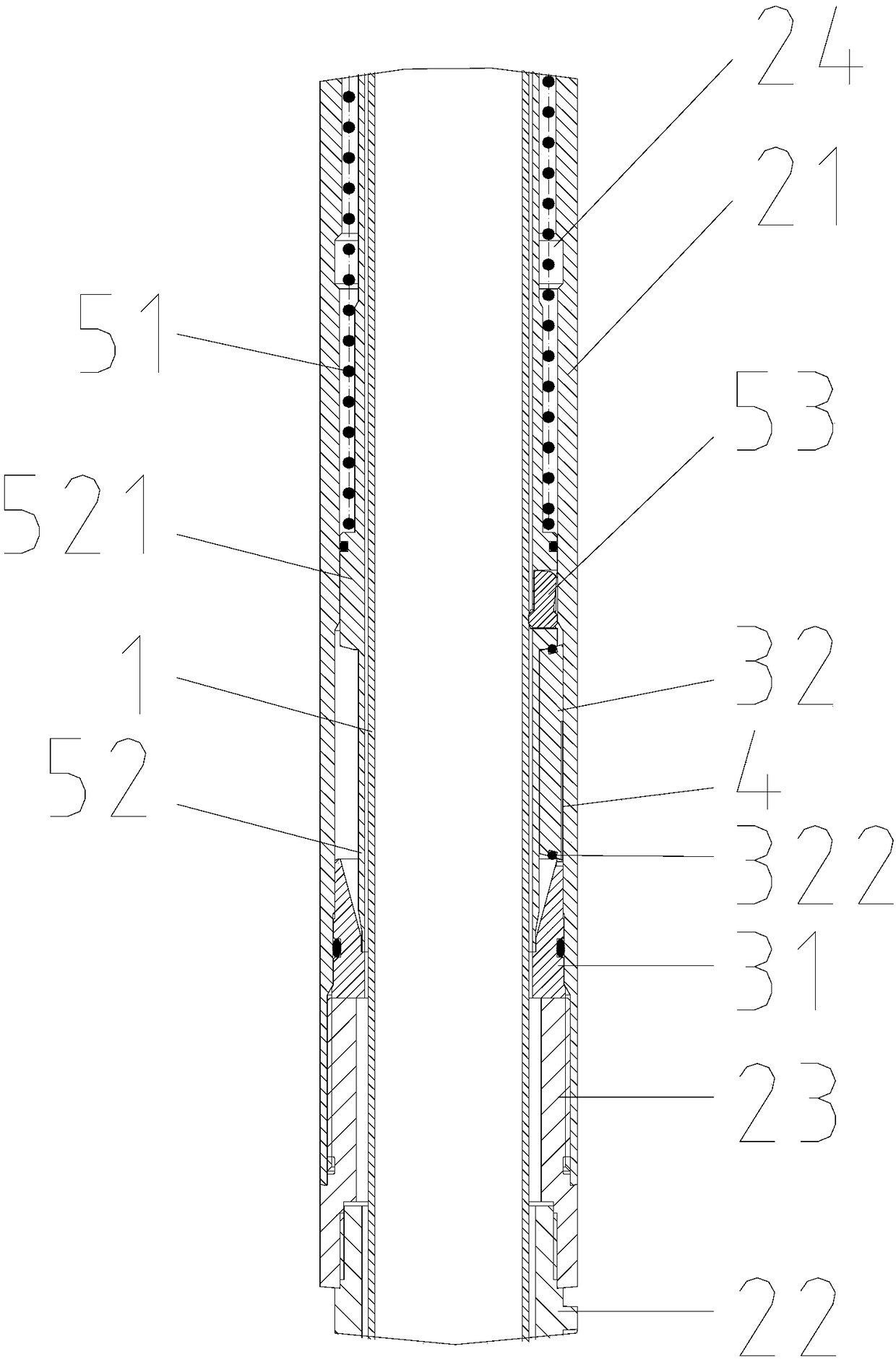
[0037] Such as figure 1 , 2 , 6, the core barrel sealing structure that can increase the sealing specific pressure disclosed by the present invention includes a core barrel 1, a drilling rig outer cylinder 2, a chain mail flap valve and a trigger mechanism, and the chain mail flap valve includes The valve seat 31 and the valve disc 32 of chain mail type, the valve seat 31 is coaxially installed on the inner wall of the outer cylinder 2 of the drilling rig, one end of the valve disc 32 is movably connected with the outer side wall of the upper end of the valve seat 31, and the top of the valve seat 31 is connected with the valve disc 32 Matching valve port sealing surface 311.

[0038] The trigger mechanism includes a trigger inner cylinder 52 and a trigger block...


PUM


Abstract

The invention relates to a core barrel sealing structure capable of increasing the sealing specific pressure. The core barrel sealing structure comprises a core barrel, a drilling machine outer barrel, a chain mail flap valve and a trigger mechanism. The chain mail flap valve comprises a valve seat and a chain mail valve clack. The trigger mechanism comprises a trigger inner barrel and a trigger block. The trigger block is arranged in a through hole in the sidewall of the trigger inner barrel. The inner wall of the drilling machine outer barrel is provided with a receding port matched with thetrigger block. When the core barrel is located in the valve seat, the valve clack is opened by 90 degrees and is located between the trigger inner barrel and the drilling machine outer barrel. When the core barrel is lifting upwards to a certain height, the valve clack returns to the top surface of the valve seat to make sealing contact with the sealing surface of a valve port, and the bottom ofthe trigger inner barrel is pressed on the valve clack. The core barrel sealing structure achieves lower-end sealing through the chain mail flap valve. The deformability of the valve clack is high andcan automatically adjust the sealing matching position and is high in matching success rate and reliable in sealing performance. Moreover, the valve clack has the reverse self-locking property duringpressure maintaining and pressure bearing and also is pressed by the fallback trigger inner barrel. The sealing specific pressure is large. The sealing performance is reliable.

Description

technical field [0001] The invention relates to the technical field of coring equipment, in particular to a core barrel sealing structure capable of increasing the sealing specific pressure. Background technique [0002] At present, in the field of pressure-holding coring, the upper end of the pressure-holding cylinder is generally sealed by a piston, and the lower end of the pressure-holding cylinder is usually sealed by a ball valve or a flap valve. The structure of the ball valve is relatively complex and occupies a large space, which limits the diameter of the drilled core. The processing technology of the ball valve is high, and when the pressure is high, the liquid in the pressure-holding cylinder will leak from the gap between the ball valve and the core cylinder. Can not maintain a higher pressure; and the existing flap valve, although the structure is simple, can maintain a higher pressure, but its valve disc is a fixed shape, can not be deformed, with a low success...

Claims


Application Information

Patent Timeline
Patent Type & Authority Applications(China)
IPC IPC(8): F16K1/20F16K1/36F16K1/46E21B25/10
CPCE21B25/10F16K1/2007F16K1/2014F16K1/205F16K1/36F16K1/46E21B25/08E21B25/12
Inventor 谢和平陈领高明忠郭峻张志龙张泽天鲁义强李聪何志强
Owner SHENZHEN UNIV
Learn More