
Test circuit and test device for detecting printed inductance

A technology for testing circuits and inductances, which is applied in the field of testing and can solve problems such as low testing accuracy

Inactive Publication Date: 2019-03-22
SHENZHEN INST OF TERAHERTZ TECH & INNOVATION CO LTD +1
View PDF3 Cites 0 Cited by
  • Summary
  • Abstract
  • Description
  • Claims
  • Application Information

AI Technical Summary

Problems solved by technology

[0004] Embodiments of the present invention provide a test circuit and a test device for detecting printed inductance, aiming to solve the problem that the distributed capacitance and distributed inductance of the existing digital bridge wiring are much larger than the distributed capacitance and distributed inductance of the tested printed circuit board, resulting in The problem of low test accuracy

Method used


Image

  • Test circuit and test device for detecting printed inductance
  • Test circuit and test device for detecting printed inductance
  • Test circuit and test device for detecting printed inductance

Examples


Embodiment Construction

[0039] In order to enable those skilled in the art to better understand the solutions of the present invention, the technical solutions in the embodiments of the present invention will be clearly described below in conjunction with the accompanying drawings in the embodiments of the present invention. Obviously, the described embodiments are the embodiment of the present invention. Some examples, but not all examples. Based on the embodiments of the present invention, all other embodiments obtained by persons of ordinary skill in the art without making creative efforts shall fall within the protection scope of the present invention.

[0040] The terms "comprising" and any variations thereof in the description and claims of the present invention and the above drawings are intended to cover non-exclusive inclusion. For example, a process, method or system, product or device comprising a series of steps or units is not limited to the listed steps or units, but optionally also inc...


PUM


Abstract

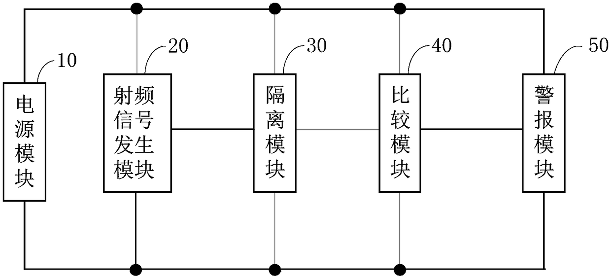
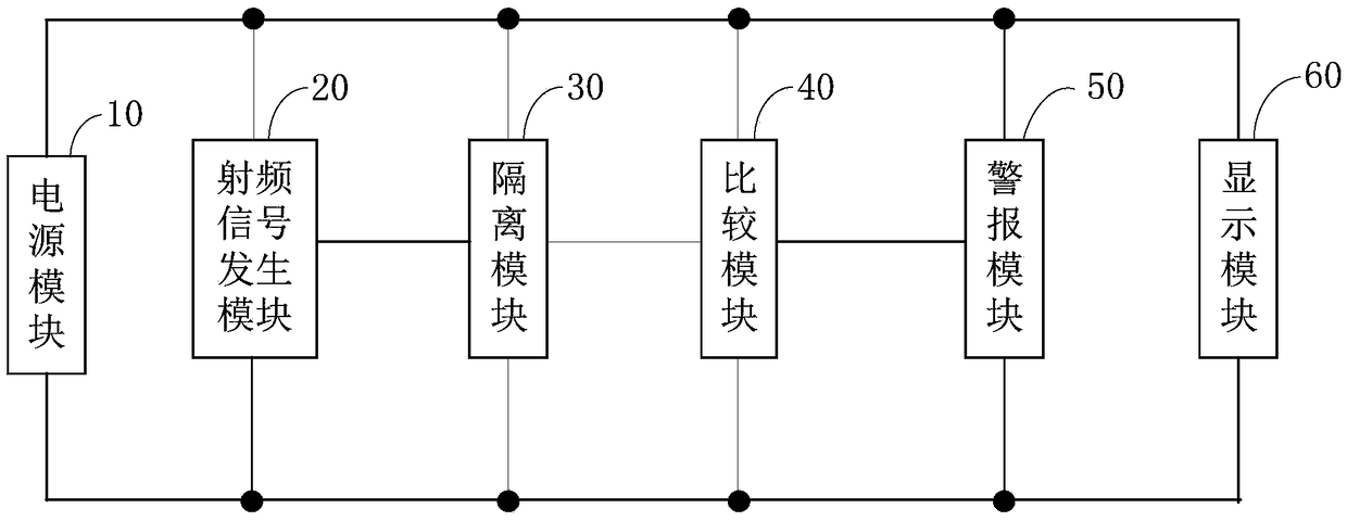
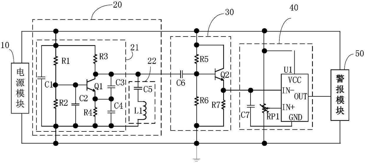
The invention belongs to the technical field of testing, and provides a test circuit and test device for detecting printed inductance. A radio-frequency signal generation module receives a power supply signal, thereby generating a radio-frequency signal and a high-frequency signal corresponding to the radio-frequency signal, the high-frequency signal is buffered and isolated through an isolation module, a frequency stabilization signal corresponding to the radio-frequency signal is output, the frequency stabilization signal is compared with a preset reference frequency signal through a comparison module, a corresponding voltage comparison signal is output, a corresponding alarm signal is output according to the voltage comparison signal through an alarm module, thereby achieving the detection of the printed inductance, when the printed inductance does not accord with a preset value, an alarm is given, and the problem that the testing precision is lower due to the fact that the distributed capacitance and distributed inductance of an existing digital electric bridge wire are much larger than those of a tested printed circuit board is solved.

Description

technical field [0001] The embodiments of the present invention belong to the technical field of testing, and in particular relate to a testing circuit and a testing device for testing printed inductance. Background technique [0002] High-frequency electrical signal carriers generally include: coaxial cables, waveguides, and printed circuit boards (Printed Circuit Board, PCB) for transmitting high-frequency circuit boards. Since high-frequency electrical signals are prone to radiation attenuation, in the process of preparing an instrument that generates high-frequency signals, higher requirements are placed on the consistency of the high-frequency printed circuit board in the instrument. If the quality of the printed circuit board cannot be controlled Strictness will lead to invalid work of patch and soldering assembly in the subsequent process. Therefore, higher requirements are also put forward for the testing of high-frequency printed circuit boards. [0003] However, t...

Claims


Application Information

Patent Timeline
Patent Type & Authority Applications(China)
IPC IPC(8): G01R31/28
CPCG01R31/2801
Inventor 全志刚李程颜世桃阎登高杨强华杨彬
Owner SHENZHEN INST OF TERAHERTZ TECH & INNOVATION CO LTD
Learn More