
Imaging gather based diffracted wave separation imaging method

An imaging gather and imaging method technology, applied in the field of diffraction wave imaging, can solve problems such as difficult to effectively separate pre-stack data, failure to obtain diffraction wave records, and large loss of diffraction waves, etc., to achieve enhanced stability and calculation Improved speed and imaging effect, high signal-to-noise ratio

Active Publication Date: 2019-03-22
CHINA PETROCHEMICAL CORP +2
View PDF2 Cites 7 Cited by
  • Summary
  • Abstract
  • Description
  • Claims
  • Application Information

AI Technical Summary

Problems solved by technology

The limitation of the former is that it is suitable for use when the underground medium structure is relatively simple and the signal-to-noise ratio is relatively high, and there are still a large number of residual reflection waves in the diffraction wave data separated by this method, and the diffraction wave loss is also large. In addition, this method can only be used for stacked seismic data, and cannot obtain diffraction wave records in the original shot domain, which is not conducive to later processing
The latter is computationally intensive for 3D seismic data, and it is generally difficult to effectively separate weak diffraction information from pre-stack data with low signal-to-noise ratio, which is also based on the diffraction information of pre-imaging data sets The main reason why the wave separation method has rarely seen good practical application results so far

Method used

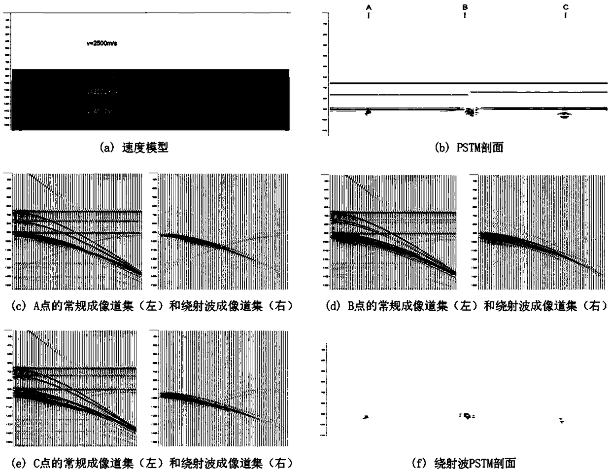
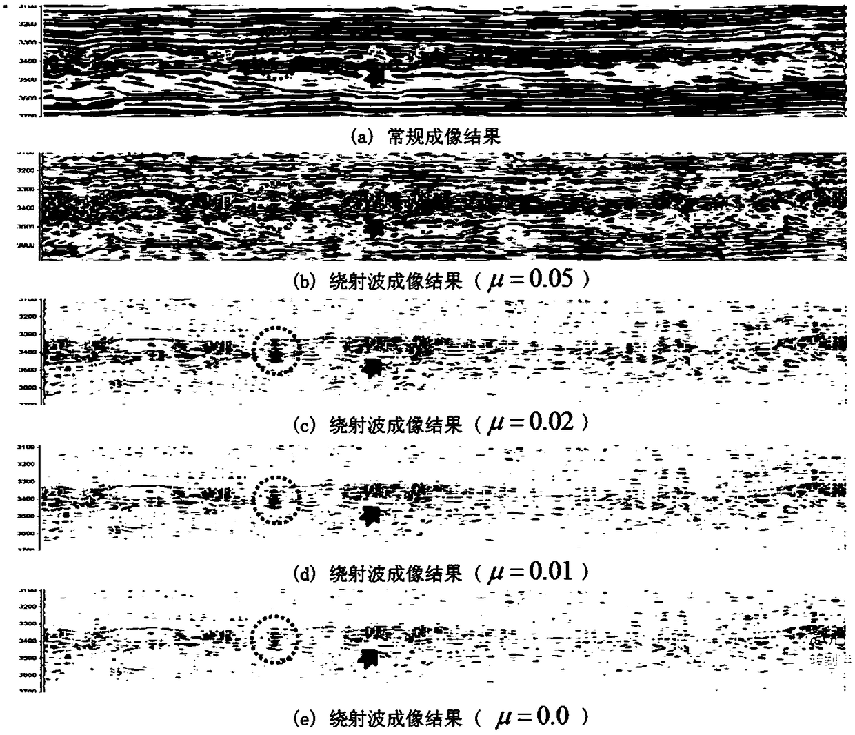
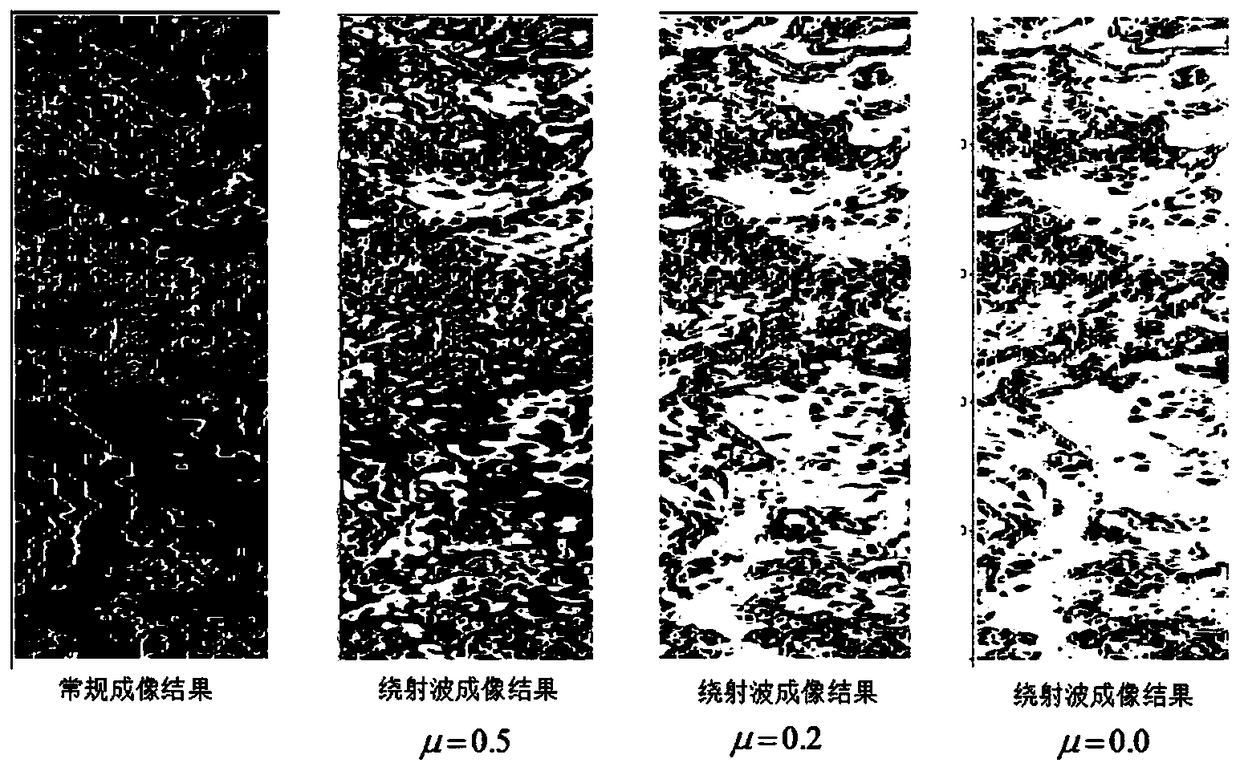

Image

  • Imaging gather based diffracted wave separation imaging method
  • Imaging gather based diffracted wave separation imaging method
  • Imaging gather based diffracted wave separation imaging method

Examples


Embodiment Construction

[0060] The following will clearly and completely describe the technical solutions in the embodiments of the present invention with reference to the accompanying drawings in the embodiments of the present invention. Obviously, the described embodiments are only some, not all, embodiments of the present invention. Based on the embodiments of the present invention, all other embodiments obtained by persons of ordinary skill in the art without creative work, any modifications, equivalent replacements, improvements, etc., shall be included in the protection scope of the present invention Inside.

[0061] According to the diffraction wave separation imaging method based on imaging gathers of the present invention, the steps of the method are:

[0062] S1. According to the basic theoretical derivation and theoretical model research, a diffraction wave separation method based on imaging gathers is obtained;

[0063] S2. For subsequent correct interpretation and analysis, retain a cer...


PUM


Abstract

The invention discloses an imaging gather based diffracted wave separation imaging method. The method comprises the following steps of firstly, obtaining an imaging gather based diffracted wave separation method according to basic theoretical derivation and theoretical model research; secondly, in order for subsequent correct interpretive analysis, retaining a certain proportion of reflected waveenergy; and finally, improving the signal-to-noise ratio of a diffracted wave separation result by using an effective signal estimation method replacing wave filtration with inversion. As the calculation is necessarily carried out in different data domains, the calculation amount of directly solving the target function solution of a diffracted wave is too large; and an iterative way is adopted tosolve the solution in the method. By using such a method, not only is the calculation amount effectively reduced, but also, as the signal-to-noise ratio of an imaging gather is relatively higher, theseparation precision of a weak diffracted wave can be improved; and thus, the stability of the separation and the reliability of the separation result of a strong diffracted wave are enhanced.

Description

technical field [0001] The invention relates to the field of diffraction wave imaging in seismic exploration, in particular to a diffraction wave separation imaging method based on imaging gathers. Background technique [0002] Diffraction waves are markers of structural and lithological anomalies and can be generated wherever discontinuities exist, such as caves, fractures, faults, pinch-outs, reefs, salt domes, weathering crust, intrusive rocks, and oil-moisture The edge of the interface is where the diffracted wave develops. The reflected wave is a comprehensive reflection of the geological background, and the diffracted wave is the reflection of geological details, which is an important information carrier for improving seismic resolution. In the raw data of seismic exploration, there are both diffracted waves and reflected waves. During the imaging process of the data, the diffracted waves and reflected waves are also uniformly migrated and imaged without distinction, ...

Claims


Application Information

Patent Timeline
IPC IPC(8): G01V1/36
CPCG01V1/36G01V2210/512G01V2210/74G01V2210/58
Inventor 朱生旺尹志恒许建国苏娟郑静静陶冶钟宇
Owner CHINA PETROCHEMICAL CORP
Learn More