Machining method and machining device of bi-metal roller sleeve and bi-metal roller sleeve

A processing method and processing device technology, applied in the field of bimetal roll sleeves, can solve the problems of incomplete bonding, gaps in the bonding layer, impurities in the bonding layer, etc., and achieve the effects of complete bonding, uniform fusion transition layer, and good mutual penetration

Inactive Publication Date: 2019-03-26
湖南四昉新材料有限公司
View PDF10 Cites 4 Cited by
  • Summary
  • Abstract
  • Description
  • Claims
  • Application Information

AI Technical Summary

Problems solved by technology

And the current bimetallic composite roll, one method is to use the pre-fabricated roll inner sleeve and roll jacket, and then use mechanical pressure to press the roll inner sleeve into the roll jacket to form a bimetallic composite roll sleeve, and then perform necessary heat treatment , such a combination method has the defects of incomplete combination and gaps in the bonding layer; another method is to fix the inner steel core and the outer mold, and cast the alloy steel liquid by bottom casting method to form the roll jacket. This combination method is also There will be defects such as impurities and bubbles in the bonding layer

Method used


Image

  • Machining method and machining device of bi-metal roller sleeve and bi-metal roller sleeve
  • Machining method and machining device of bi-metal roller sleeve and bi-metal roller sleeve
  • Machining method and machining device of bi-metal roller sleeve and bi-metal roller sleeve

Examples


Embodiment 1

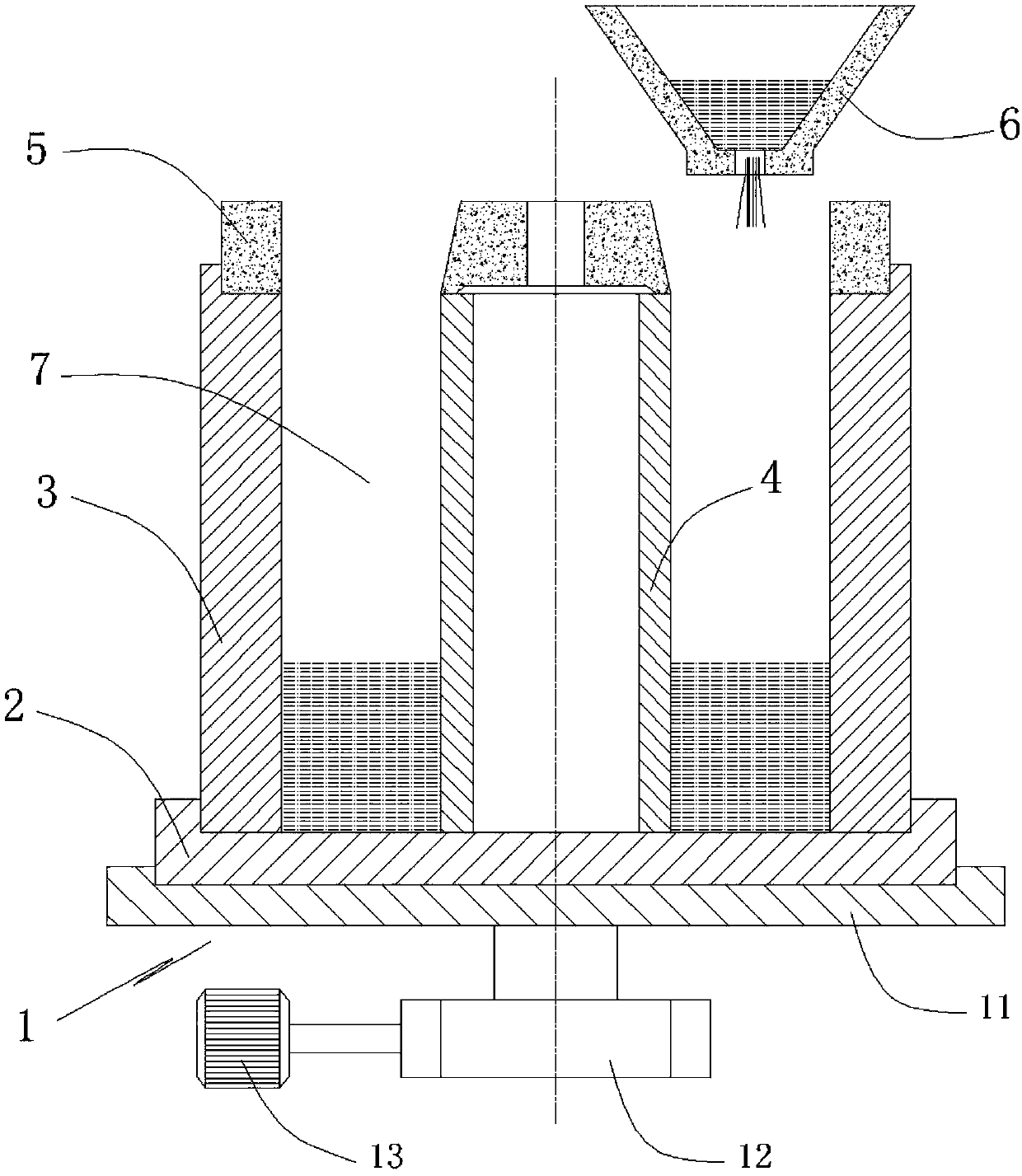
[0046] Please refer to Figure 1 to Figure 3 , the processing method of a kind of bimetal roll sleeve of present embodiment, this processing method comprises the following steps:

[0047] The rotating mechanism 1, the casting base plate 2 and the outer steel mold 3 for processing the bimetal roll sleeve are prepared in advance, the casting base plate 2 is fixed on the rotating mechanism 1, and the outer steel mold 3 is installed on the casting base plate 2. Wherein, the rotating mechanism 1 includes a turntable 11 , a reducer 12 and a motor 13 , the turntable 11 drives the casting base plate 2 to rotate under the drive of the motor 13 , and the speed of rotation can be adjusted by the reducer 12 .

[0048] Fix the inner steel core 4 on the casting base plate 2, form a casting space 7 between the inner steel core 4 and the outer steel mold 3, place the casting sand mold 5 on the outer steel mold 3 and the inner steel core 4, adjust the casting cup 6 position so that the liquid...

Embodiment 2

[0057] Please refer to Figure 4 to Figure 6 , a processing device for a bimetallic roll sleeve of the present embodiment is used in the processing method described in Embodiment 1. The processing device includes: a rotating mechanism 1, a casting base plate 2, an outer steel mold 3 and a casting cup 6, and the rotating mechanism 1 is fixedly installed at a predetermined location, the casting bottom plate 2 is detachably embedded on the rotating mechanism 1, and the outer steel mold 3 is detachably installed on the casting bottom plate 2. Wherein, the rotating mechanism 1 includes a turntable 11 , a reducer 12 and a motor 13 , the turntable 11 drives the casting base plate 2 to rotate under the drive of the motor 13 , and the speed of rotation can be adjusted by the reducer 12 .

[0058] The position of the casting cup 6 is adjustable and erected above the outer steel mold 3. When casting, an inner steel core 4 is fixed on the casting bottom plate 2, and the position of the ca...

Embodiment 3

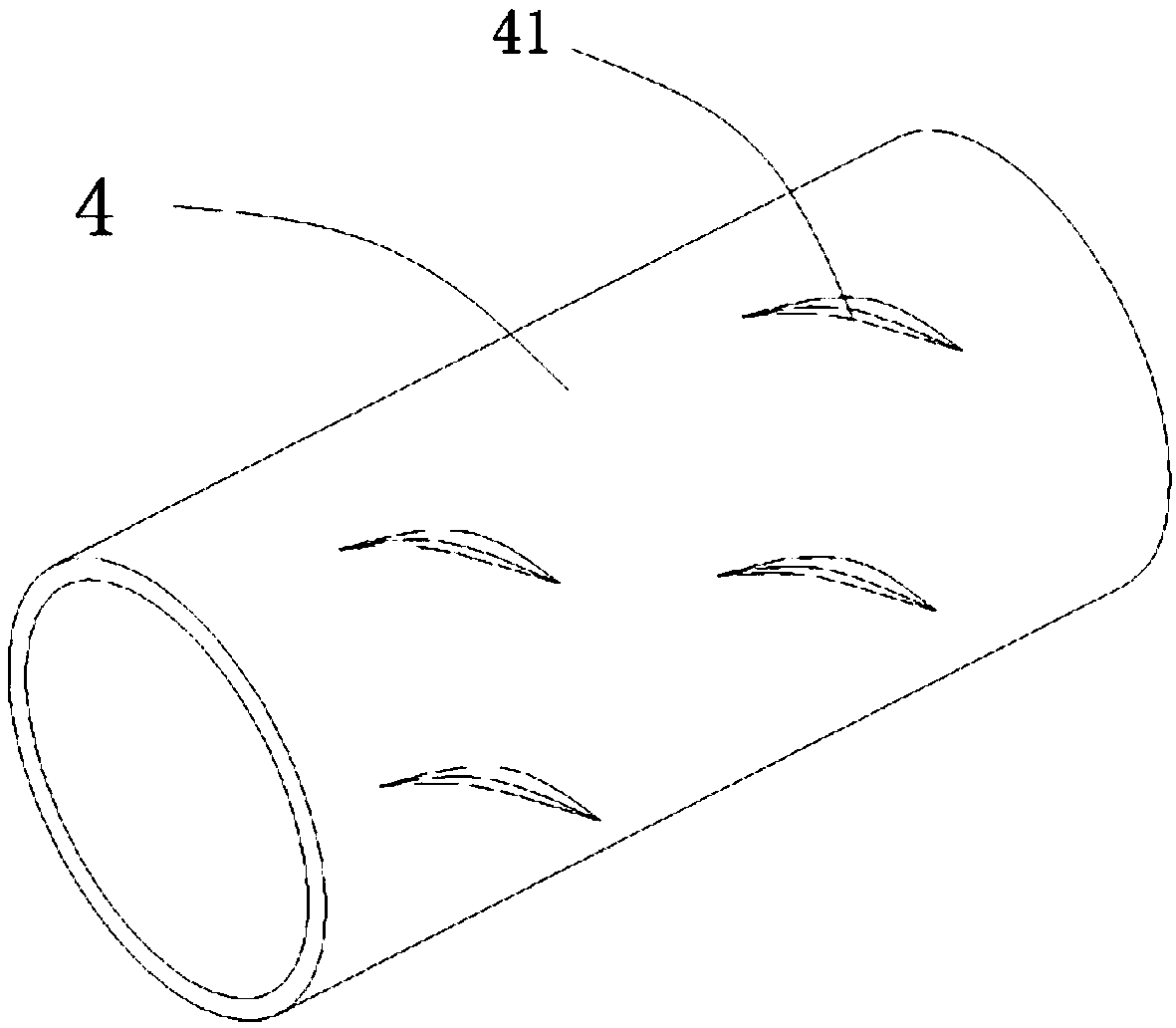
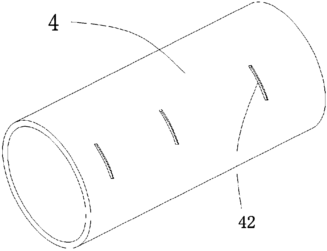
[0065] Please refer to Figure 7 to Figure 9, a kind of bimetallic roll sleeve of this embodiment is made by using the processing method described in Embodiment 1. The bimetallic roll sleeve includes: an inner steel core 4 and a roll jacket 8, and the inner steel core 4 is a prefabricated ordinary steel pipe. The roll jacket 8 is a high-speed steel alloy jacket cast-in-place on the outside of the inner steel core 4 . When the roll jacket 8 is cast-in-place, the molten alloy steel and the molten steel on the outer wall of the inner steel core 4 infiltrate each other to form a molten transition layer 9 .

[0066] Preferably, the outer peripheral surface of the inner steel core 4 is provided with convex ribs 41 or grooves 42, and the protruding height of the convex ribs 41 is 1 / 30-1 / 20 of the wall thickness of the inner steel core 4, or the concave depth of the groove 42 It is 1 / 30-1 / 20 of the wall thickness of the inner steel core 4.

[0067] Still preferably, the roll jacket 8...


PUM


Abstract

The invention discloses a machining method of a bi-metal roller sleeve. The machining method of the bi-metal roller sleeve includes the following steps that a rotating mechanism, a casting bottom plate and an outer steel mold used for machining the bi-metal roller sleeve are prepared in advance; an inner steel core is fixed to the casting bottom plate, and a casting space is formed between the inner steel core and the outer steel mold; the rotating mechanism is started, the rotating speed of the rotating mechanism is set to be 25-75 r / min, a casting cup is opened, alloy steel liquid is injected into the casting space, and the roller outer sleeve is formed after the alloy steel liquid is cooled. The invention further discloses a machining device used for the method and the bi-metal roller sleeve machined and produced through the method. In this way, according to the roller outer sleeve manufactured in a cast-in-place manner, due to the fact that when the high temperature alloy steel liquid is combined with the inner steel core in the cast-in-place process, part of the structure of the outer wall of the inner steel core can be melted, thus combination of the alloy steel liquid and the inner steel core is firmer, interinfiltration between the two is more sufficient, and a perfectly combined transition layer is formed.

Description

technical field [0001] The invention relates to the technical field of metal rolls and processing, in particular to a processing method of a bimetallic roll sleeve, a processing device used in the processing method, and a bimetallic roll sleeve produced by the processing method. Background technique [0002] The roll is the most important consumable part in steel rolling production. It is also known as the "mother of steel". my country produces about 800,000 tons of rolls every year. Most of the currently used rolls are traditional integral rolls or sleeve-type composite rolls, and sleeve-type composite rolls are currently only used in the field of bar and wire rolling. The sleeve-type composite roll is composed of a roll shaft and a roll sleeve. The roll sleeve is nested outside the roll shaft and is driven by the roll shaft to contact the steel billet to cause plastic deformation of the steel billet. The roll sleeve needs to withstand a large rolling force when in use, an...

Claims


Application Information

Patent Timeline
Patent Type & Authority Applications(China)
IPC IPC(8): B22D19/08B22D19/16B22D27/08C22C38/16C22C38/12C22C38/08C22C38/04C22C38/02C21D1/26C21D9/38
CPCB22D19/08B22D19/16B22D27/08C21D1/26C21D9/38C22C38/002C22C38/02C22C38/04C22C38/08C22C38/12C22C38/16
Inventor 罗教武李茂华徐树基周文光
Owner 湖南四昉新材料有限公司
Why Eureka
Try Eureka