Method to restore an airfoil leading edge

a leading edge and airfoil technology, applied in the field of laser welding, can solve the problems of blade leading edge damage, difficult repair strategies for the gas turbine engine, and the inability to easily remove the damaged airfoil for repair

Inactive Publication Date: 2006-03-30
HONEYWELL INT INC
View PDF12 Cites 55 Cited by
  • Summary
  • Abstract
  • Description
  • Claims
  • Application Information

AI Technical Summary

Problems solved by technology

The development of the blisk as a gas turbine engine component has presented challenges with respect to repair strategies.
Individual airfoils are now permanently attached to the rotor disk, which means that damaged airfoils cannot easily be removed for repair, as has been done with individual turbine blades.
Blade leading edge damage, for example, is a common failure experienced in blisks.
The leading edge is subject to foreign object damage or erosion after a period of service time.
The option of throwing out worn engine components such as turbine blisks and replacing them with new ones is not an attractive alternative.
Blisks are very expensive due to costly material and manufacturing processes.
Disadvantageously, the superalloys generally are very difficult to weld successfully.
Traditional repair methods have proven less than satisfactory for superalloy materials.
However, at such an elevated temperature the turbine blade may experience heat cracking and fracturing, rendering the blade unusable for further engine service.
Other welding techniques similarly suffer from a lack of thermal control and provide too much localized heat during welding to render an effective repair with superalloy blisk airfoils.
Superalloys are susceptible to microcracking during localized heating.
Moreover, the complex geometry of the airfoil, and particularly, the shape of the leading edge, makes it difficult to deposit filler or cladding material thereon.
It has proven difficult to provide filler or cladding material across a high stress region with sufficient strength and adherence such that the airfoil can be returned to service.

Method used


Image

  • Method to restore an airfoil leading edge
  • Method to restore an airfoil leading edge
  • Method to restore an airfoil leading edge

Examples


Embodiment Construction

[0024] The following detailed description of the invention is merely exemplary in nature and is not intended to limit the invention or the application and uses of the invention. Furthermore, there is no intention to be bound by any theory presented in the preceding background of the invention or the following detailed description of the invention. Reference will now be made in detail to exemplary embodiments of the invention, examples of which are illustrated in the accompanying drawings. Wherever possible, the same reference numbers will be used throughout the drawings to refer to the same or like parts.

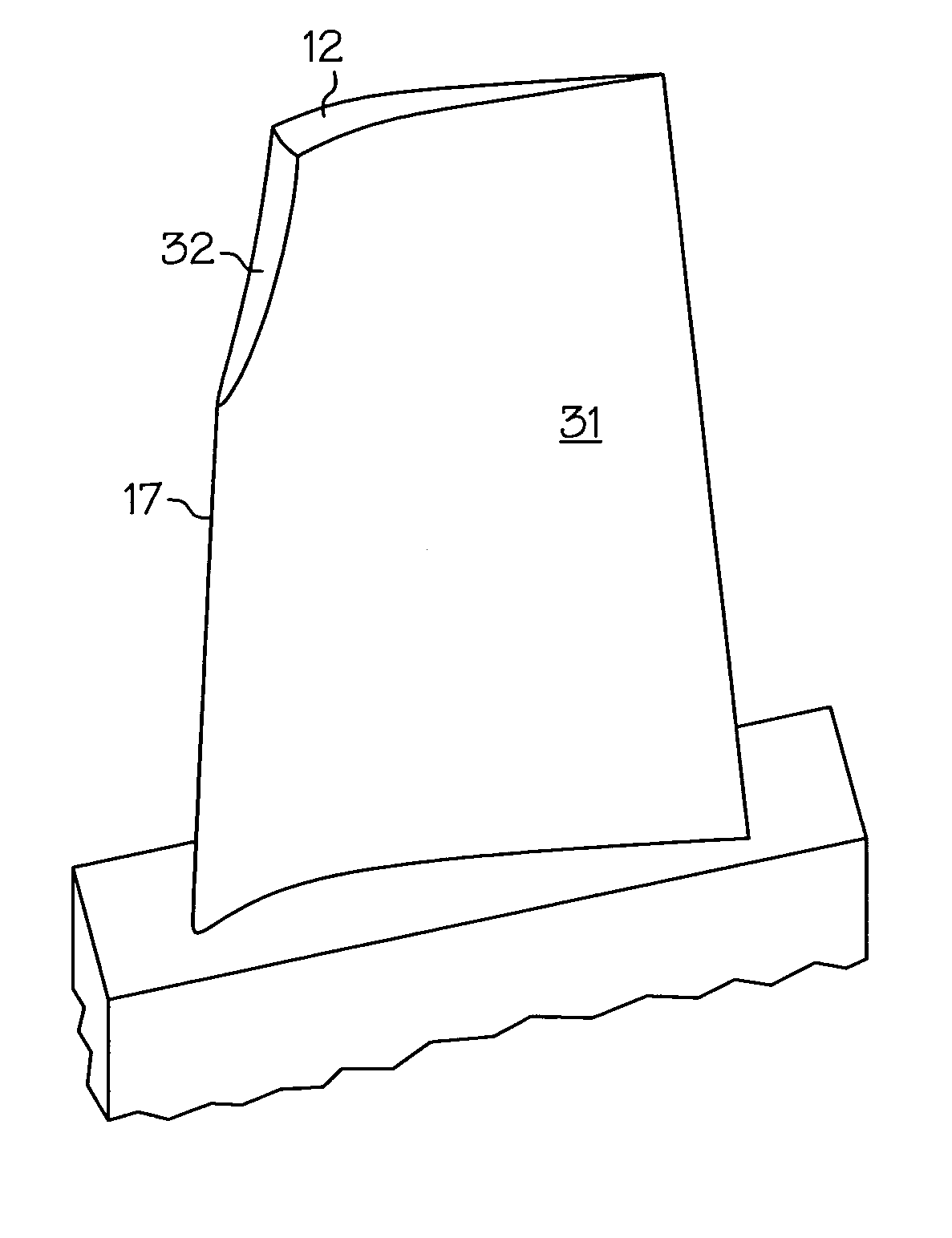
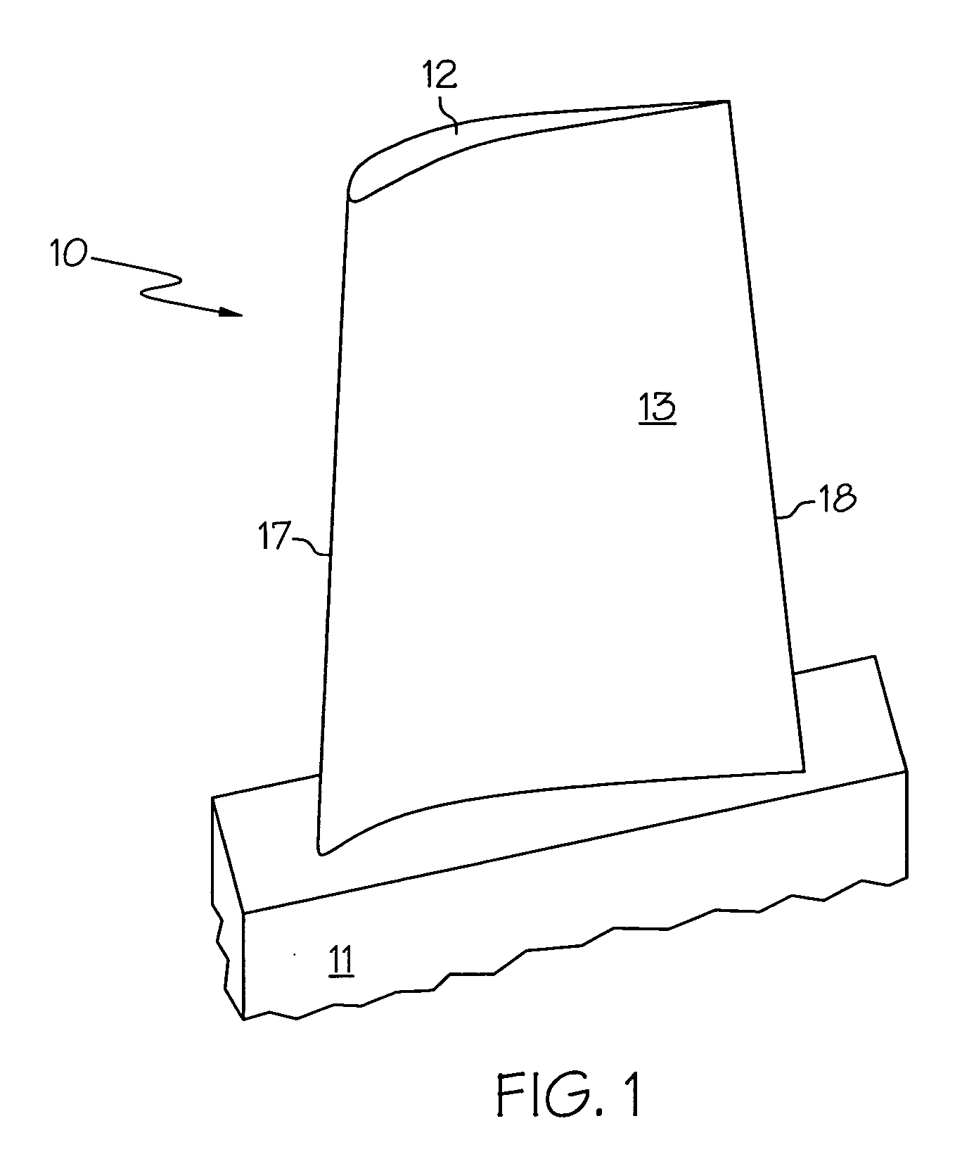
[0025] A typical airfoil 10 of a turbine blisk is illustrated in FIG. 1. Such a blade may have a different geometric and dimension design, depending on the engine model and its application. For a typical aero-engine, a turbine blisk airfoil is typically a few inches in length. Airfoil 10 is characterized by a complex geometry that changes in three dimensions. A gas turbine airfoil ...


PUM

PropertyMeasurementUnit
areaaaaaaaaaaa
temperaturesaaaaaaaaaa
poweraaaaaaaaaa

Abstract

The present invention provides methods and apparatus to restore a blade leading edge on a gas turbine engine component such as an airfoil of a turbine blisk. The method utilizes welding image technology and power control systems in order to provide effective welding with superalloy materials such as Inconel 713 and Inconel 625. The method includes machining away a damaged leading edge and providing a repaired region through successive depositions of superalloy powder filler through laser fusion welding. Deposition material is added until the repaired region exceeds the original dimensions of the airfoil. The airfoil is then machined and finished to return it to original airfoil dimensions.

Description

FIELD OF THE INVENTION [0001] The present invention relates to laser welding. Additionally the invention relates to the apparatus and techniques used to repair the leading edge of airfoils that have suffered degradation or wear. More particularly, the invention relates to a method to restore, by laser welding techniques with powder filler, the leading edge on the blades of turbine blisks that have been eroded by foreign object damage. BACKGROUND OF THE INVENTION [0002] Turbine engines are used as the primary power source for many types of aircraft. The engines are also auxiliary power sources that drive air compressors, hydraulic pumps, and industrial gas turbine (IGT) power generation equipment. Further, the power from turbine engines is used for stationary power supplies such as backup electrical generators for hospitals and the like. [0003] Most turbine engines generally follow the same basic power generation procedure. Compressed air generated by axial and / or radial compressors ...

Claims


Application Information

Patent Timeline
Patent Type & Authority Applications(United States)
IPC IPC(8): F04D29/38
CPCB23P6/007F01D5/005F05D2230/30F05D2230/232B23K26/3206B23K26/3213B23K35/0244B22F2007/068B23K35/3033B23K35/304C22C19/055C22C19/056B23K26/345B23K26/32B23K26/342B23K2101/001B23K2103/18B23K2103/26B23K2103/50
Inventor GUO, WENRENTERIA, FEDERICO
Owner HONEYWELL INT INC
Why Eureka
Try Eureka