Bobbin chamfering device

A chamfering device and package yarn technology, which is applied in the directions of transportation and packaging, dust removal, and delivery of filamentous materials, etc., can solve problems such as low efficiency, and achieve the effects of improving efficiency, reducing pollution, and improving convenience

Inactive Publication Date: 2019-03-26
WUHU FUCHUN DYEING & WEAVING
0 Cites 4 Cited by

AI-Extracted Technical Summary

Problems solved by technology

For this reason, the upper and lower shoulders should be "rounded", and the simplest way is "chamfering". The existing chamfering devices use two hemispherical containers to squeeze the upper and lower ends of the...

Abstract

The invention provides a bobbin chamfering device. The bobbin chamfering device comprises a conveyor belt, wherein mounting blocks are symmetrically arranged at the two sides of the conveyor belt; a chamfering channel is arranged on the mounting blocks; the chamfering channel is positioned above the conveyor belt; the chamfering channel is wide in two sides and is narrow in middle; the chamferingchannel comprises an upper chamfering plate and a lower chamfering plate; the two sides of each of the upper chamfering plate and the lower chamfering plate are arc-shaped; more than one rotary plateis arranged on the conveyor belt; a bobbin placing frame is arranged on the rotary plate; a movable empty slot is formed in the middle of the lower chamfering plate; and the bobbin placing frame passes through the movable empty slot and extends into the chamfering channel. According to the bobbin chamfering device provided by the invention, the upper chamfering plate and the lower chamfering plateare combined into the chamfering channel, so that chamfering is performed in a bobbin conveying process; and meanwhile, multiple bobbins can be chamfered at the same time, so that chamfering efficiency is improved, and therefore, the bobbin chamfering device is suitable for being used in production.

Application Domain

Filament handlingDirt cleaning

Technology Topic

Bobbin

Image

  • Bobbin chamfering device
  • Bobbin chamfering device

Examples

  • Experimental program(1)

Example Embodiment

[0012] In order to deepen the understanding of the present invention, the present invention will be further described in detail below in conjunction with examples. The examples are only used to explain the present invention and do not constitute a limitation on the protection scope of the present invention.
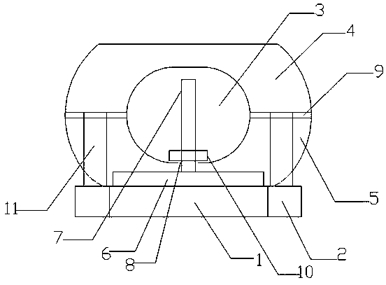
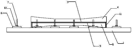
[0013] Such as Figure 1-2 As shown, this embodiment provides a package chamfering device, which includes a conveyor belt 1. The conveyor belt 1 is provided with mounting blocks 2 symmetrically on both sides, and the mounting block 2 is provided with a chamfering channel 3, which is located above the conveyor belt 1. The chamfering channel 3 is wide on both sides and narrow in the middle. The chamfering channel 3 includes an upper chamfered plate 4 and a lower chamfered plate 5. Both sides of the upper chamfered plate 4 and the lower chamfered plate 5 are curved, and the conveyor belt 1 is set up There is a rotating plate 6, the rotating plate 6 is provided with more than one, the rotating plate 6 is provided with a cheese placing rack 7, and the lower chamfering plate 5 is provided with a movable slot 8 in the middle, and the cheese placing rack 7 extends through the movable slot 8 Into the chamfer channel 3. A dust suction pipe 9 is arranged between the upper chamfered plate 4 and the lower chamfered plate 5. A fixed placement block 10 is provided at the lower end of the cheese placement frame 7. Two ends of the upper chamfered plate 4 are provided with lifting support columns 11.
[0014] In this embodiment, the cheese is placed on the cheese holder 7, and the rotating plate 6 drives the cheese to be conveyed on the conveyor belt 1 while rotating. When the rotating plate 6 is conveyed under the chamfering channel 3, the cheese holder 7 The movable empty slot 8 enters the chamfering channel 3, the upper chamfering plate 4 and the lower chamfering plate 5 chamfer the cheese; the lifting support columns 11 set at both ends of the upper chamfering plate 4 can be adjusted according to the height of the cheese , Can chamfer cheeses of different heights; the dust suction pipe 9 between the upper chamfering plate 4 and the lower chamfering plate 5 absorbs the yarn fluff generated during the chamfering process.

PUM

no PUM

Description & Claims & Application Information

We can also present the details of the Description, Claims and Application information to help users get a comprehensive understanding of the technical details of the patent, such as background art, summary of invention, brief description of drawings, description of embodiments, and other original content. On the other hand, users can also determine the specific scope of protection of the technology through the list of claims; as well as understand the changes in the life cycle of the technology with the presentation of the patent timeline. Login to view more.

Similar technology patents

Compositing Windowing System

InactiveUS20100058229A1minimal costimprove efficiency
Owner:QUALCOMM INC

Control circuit and method for a buck-boost power converter

ActiveUS20110074373A1improve efficiencyminimize output ripple
Owner:RICHTEK TECH

Classification and recommendation of technical efficacy words

  • Improve convenience
  • Improve efficiency

Image display method and apparatus

ActiveUS20130040623A1improve conveniencemaximize utility
Owner:LG ELECTRONICS INC

Voice control method and device

Owner:LE SHI ZHI XIN ELECTRONICS TECH TIANJIN

Continuously operable seat-reclining device for vehicles

InactiveUS20050110322A1actuate load be reduceimprove convenience
Owner:DAS CO LTD
Why Eureka
Try Eureka