Glass test tube high-temperature drying and disinfection device

A high-temperature drying and disinfection device technology, applied in the direction of drying gas arrangement, disinfection, drying room/container, etc., can solve the problems of uneven heating of test tubes, secondary pollution of test tubes, easy water accumulation, etc., and achieve comprehensive and thorough drying and disinfection. Convenient drying and disinfection, uniform heating effect

Inactive Publication Date: 2019-03-26
吴迪
View PDF5 Cites 7 Cited by
  • Summary
  • Abstract
  • Description
  • Claims
  • Application Information

AI Technical Summary

Problems solved by technology

[0002] The test tube is a common instrument in the laboratory. It is mainly used as a reaction container for a small amount of reagents. Most of the test tubes are made of glass, and most of them have a deep tubular structure. After the test tube is used, it should be cleaned in time to prevent reagent residue. , cause pollution, but also affect the next use
[0003] Existing methods for cleaning test tubes include the principle of steaming or flushing with water to clean the test tubes. After cleaning, there will be moisture remaining on the inner and outer walls of the test tubes, which requires drying the test tubes. There are two main methods of drying. One is to dry the test tubes naturally. This method takes a long time, and the test tubes are easily polluted twice during the natural air drying process, which is very inconvenient. The other is to use mechanical equipment to dry the test tubes. For drying, because most of the test tubes have a deep tubular structure, the test tubes are heated unevenly during drying, and the inner bottom of the test tube is not easy to dry, and the bottom of the test tube is mostly hemispherical, which leads to the accumulation of the inner bottom of the test tube. Water is not easy to dry; therefore, in order to solve the above problems, it is necessary to develop a high-temperature drying and disinfection device for glass test tubes

Method used


Image

  • Glass test tube high-temperature drying and disinfection device
  • Glass test tube high-temperature drying and disinfection device
  • Glass test tube high-temperature drying and disinfection device

Examples


Embodiment Construction

[0021] The technical solutions of the present invention will be further specifically described below through embodiments and in conjunction with the accompanying drawings.

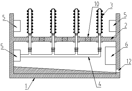
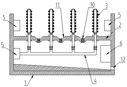
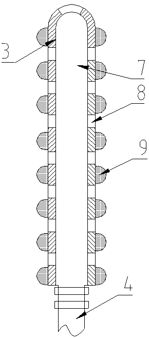
[0022] Such as figure 1 , figure 2 , image 3 As shown, a glass test tube high-temperature drying and disinfection device includes a box body 1, a partition 2, a drying rod 3, a ventilation pipe 4, a hot air circulation device 5 and a control device 6.

[0023] Wherein, a partition 2 is arranged inside the box body 1, and a leaking net 10 is arranged on the partition 2, which is convenient for collecting and processing the residual water on the test tube. The partition 2 is provided with a drying rod 3, and the bottom of the drying rod 3 Connect the ventilation pipe 4, the ventilation pipe 4 passes through the partition 2 and connects with the hot air circulation device 5 arranged under the partition 2 in the box body 1, and the control device 6 is also installed under the partition 2 in the box body 1,...


PUM


Abstract

The invention discloses a glass test tube high-temperature drying and disinfection device. The glass test tube high-temperature drying and disinfection device comprises a box body, a clapboard, dryingbars, a ventilation pipe, hot air circulating devices and a control device, wherein the box body is internally provided with the clapboard, the clapboard is provided with the drying bars, the bottomends of the drying bars are connected with the ventilation pipe, the ventilation pipe penetrates through the clapboard to be connected with one of the hot air circulating devices arranged below the clapboard inside the box body, the position, located below the clapboard, inside the box body is further provided with the control device, the control device is in electrical connection with the hot aircirculating devices, each drying bar is internally hollow and provided with a cavity to communicate with the ventilation pipe, and the side wall of each drying bar is further provided with a plurality of ventilation holes. By means of the glass test tube high-temperature drying and disinfection device, rapid and effective drying and disinfection can be performed on the inner portions of test tubes, the inner portions of the test tubes are heated evenly, and meanwhile, water accumulation and residue of the inner portions of the test tubes can be prevented.

Description

technical field [0001] The invention relates to a drying and disinfection device, in particular to a high-temperature drying and disinfection device for glass test tubes. Background technique [0002] The test tube is a common instrument in the laboratory. It is mainly used as a reaction container for a small amount of reagents. Most of the test tubes are made of glass, and most of them have a deep tubular structure. After the test tube is used, it should be cleaned in time to prevent reagent residue. , causing pollution, but also affect the next use. [0003] Existing methods for cleaning test tubes include the principle of steaming or flushing with water to clean the test tubes. After cleaning, there will be moisture remaining on the inner and outer walls of the test tubes, which requires drying the test tubes. There are two main methods of drying. One is to dry the test tubes naturally. This method takes a long time, and the test tubes are easily polluted twice during th...

Claims


Application Information

Patent Timeline
Patent Type & Authority Applications(China)
IPC IPC(8): F26B9/10F26B25/18F26B21/00F26B21/06F26B25/08F26B25/10A61L2/06
CPCA61L2/06A61L2202/23F26B9/10F26B21/004F26B21/06F26B25/08F26B25/10F26B25/18
Inventor 吴迪
Owner 吴迪
Why Eureka
Try Eureka