Mounting structure of grid-method mixed sampling device for outlet flue gas of denitrification device

A technology of mixed sampling and installation structure, applied in the direction of sampling device, measuring device, sampling, etc.

Inactive Publication Date: 2019-03-26
南京博沃科技发展有限公司
View PDF0 Cites 4 Cited by
  • Summary
  • Abstract
  • Description
  • Claims
  • Application Information

AI Technical Summary

Problems solved by technology

[0004] Accordingly, the flue gas sampling points at the denitrification outlet generally need to be designed to be 25 to 36 to meet the recommended requirements of national standards. The existing measurement and sampling methods need to be upgraded urgently

Method used


Image

  • Mounting structure of grid-method mixed sampling device for outlet flue gas of denitrification device
  • Mounting structure of grid-method mixed sampling device for outlet flue gas of denitrification device
  • Mounting structure of grid-method mixed sampling device for outlet flue gas of denitrification device

Examples


Embodiment 1

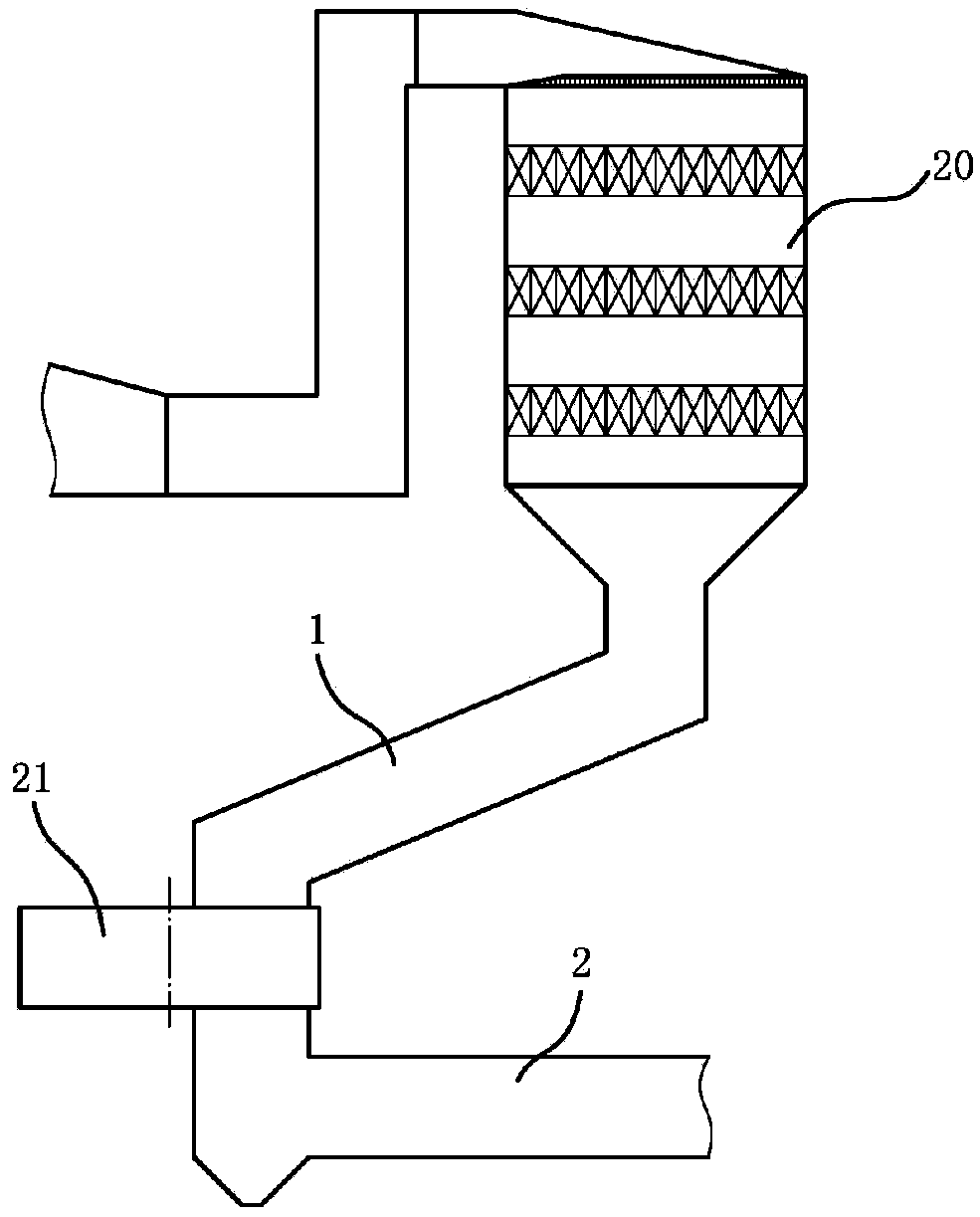
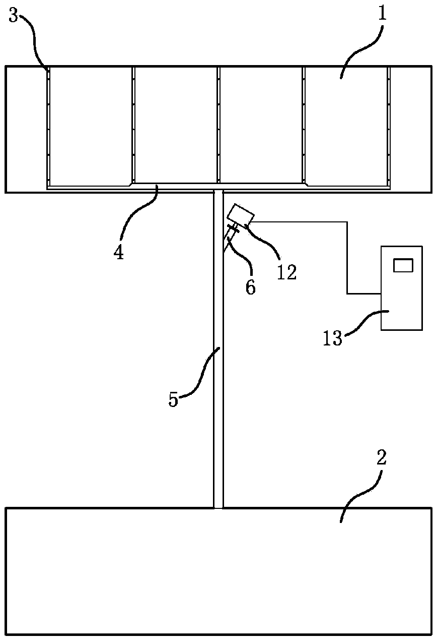
[0037] Such as figure 2 As shown, the installation structure of a flue gas grid method mixed sampling device at the outlet of a denitrification device includes the outlet flue of the denitrification device and the outlet flue of the air preheater, and also includes multi-point sampling pipes, variable cross-section confluence pipes, sampling master pipes and Sampling cavity of NOx measuring instrument; there are 5 multi-point sampling tubes, and they are vertically installed on the cross-section of the outlet flue of the denitrification device at equal intervals, and each multi-point sampling tube is equipped with 5 sampling holes; Two different cross-sectional sizes, the cross-sectional size gradually increases from both ends to the middle position, and the variable cross-section confluence pipe has a symmetrical structure at both ends; Both are connected with the variable cross-section confluence pipe; the sampling main pipe is arranged outside the outlet flue of the denitrif...

Embodiment 2

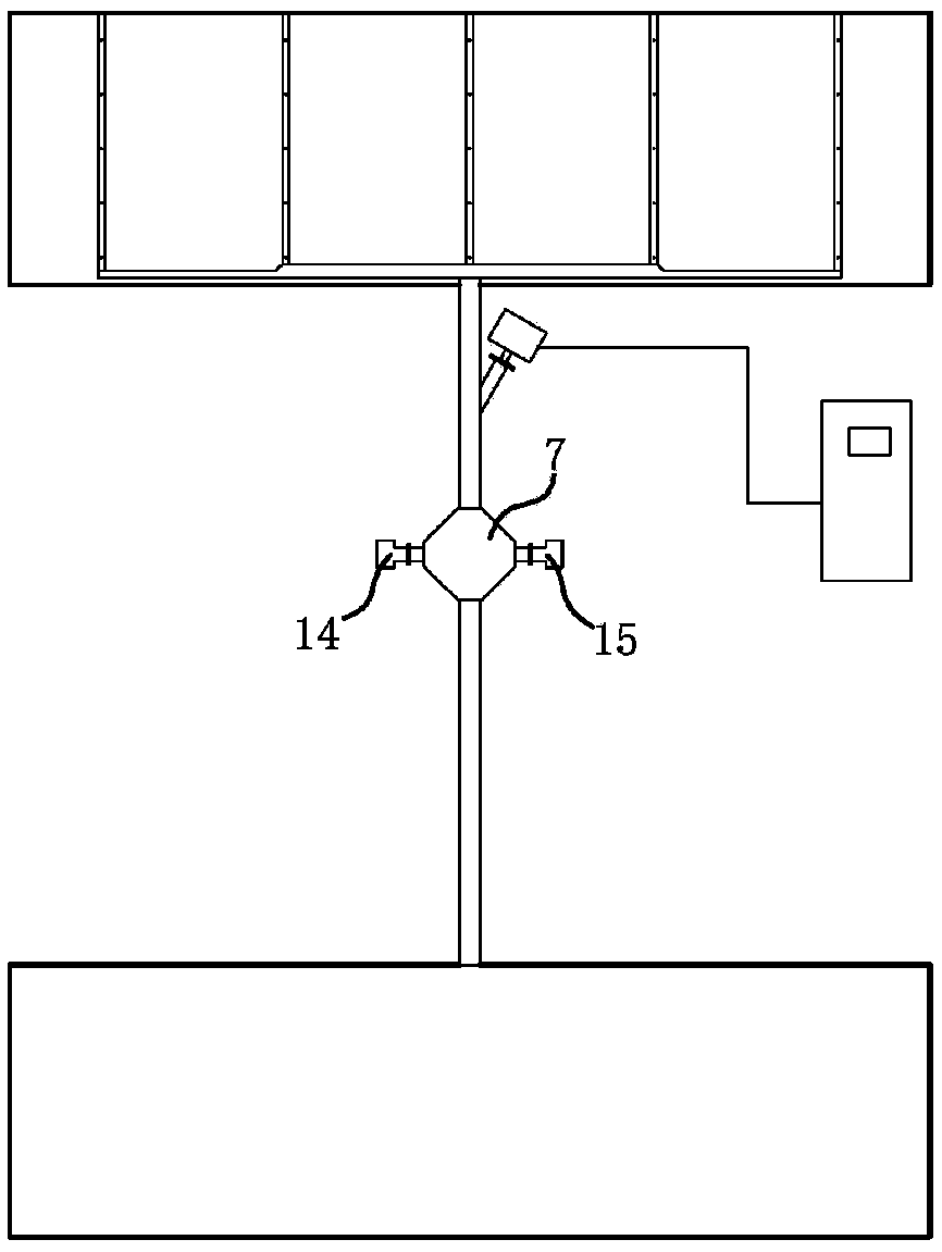
[0041] Such as image 3 As shown, it is basically the same as in Example 1, the difference is: the sampling main pipe is also provided with NH 3 Fugitive gauge sampling chamber, NH 3 The sampling cavity of the fugitive measuring instrument is located downstream of the sampling cavity of the NOx measuring instrument, NH 3 The sampling cavity of the escape measuring instrument is a quadrilateral structure, and the two opposite corners of the sampling cavity are connected in series on the sampling mother pipe, and the other two opposite corners are respectively equipped with the transmitting end and the receiving end of the laser probe.

Embodiment 3

[0043] Such as Figure 4 As shown, it is basically the same as Example 2, the difference is: in order to prevent the low differential pressure of the air preheater during the start and stop phase, the low temperature of the flue gas and the low flow rate of the flue gas in the sampling device lead to the occurrence of ash and condensate in the above sampling device ( condensate will further lead to vicious ash plugging), the sampling main pipe is also equipped with a restrictor, anti-blocking protection valve, differential pressure transmitter and temperature measuring point, wherein the restrictor is located upstream of the anti-blocking protection valve, all The measuring instrument is located upstream of the restrictor, and the positive pressure end of the differential pressure transmitter is connected upstream of the restrictor, NH 3 On the sampling main pipe downstream of the sampling cavity of the escape measuring instrument, the negative pressure end of the differential...


PUM


Abstract

The invention discloses a mounting structure of a grid-method mixed sampling device for outlet flue gas of a denitrification device. The mounting structure comprises a denitrification device outlet flue and an air pre-heater outlet flue, and further comprises multi-point sampling pipes, a variable-section collection pipe, a sampling main pipe and a sampling cavity; two or more than two multi-pointsampling pipes are arranged and mounted on the section of the denitrification device outlet flue at equal distance; the variable-section collection pipe is mounted in the denitrification device outlet flue; the bottoms of the multi-point sampling pipes are communicated with the variable-section collection pipe; one end of the sampling main pipe is communicated with the variable-section collectionpipe and the other end of the sampling main pipe is communicated with the air pre-heater outlet flue; and the sampling cavity is arranged on the sampling main pipe. The mounting structure is especially applicable to mixed sampling and measurement of NOx and / or ammonia escaping concentration of a denitrification device outlet; a sampling manner meets the recommended standards of China; a collectedflue gas sample can rapidly and automatically enter a measurement instrument by utilizing the pressure difference of the denitrification device outlet flue and the air pre-heater outlet flue; and themounting structure has good measurement timeliness, is stable and reliable in sampling and has the remarkable advantages of low cost, less maintenance working amount and the like.

Description

technical field [0001] The invention relates to the measurement technology of flue gas components at the denitrification outlet of a large coal-fired power station, in particular to the monitoring of NOx and NH in the flue gas at the outlet of a denitrification device 3 Mixed sampling device for fugitive concentrations. Background technique [0002] At present, in order to monitor the combustion status of coal-fired power plant boilers and the operation status of downstream denitrification devices, an online continuous flue gas analysis system is often installed at the outlet of the denitrification device. The monitoring parameters include NOx, ammonia slip, O 2 Concentration etc. However, the conventional measurement technology is to take 1 to 3 measurement points on the cross-section of the outlet flue of the denitrification device, and measure the flue gas parameters at the outlet of the denitrification device on a point-by-area basis. In fact, with the development of l...

Claims


Application Information

Patent Timeline
Patent Type & Authority Applications(China)
IPC IPC(8): G01N1/24
CPCG01N1/2258
Inventor 韦红旗石伟伟李文霞
Owner 南京博沃科技发展有限公司
Why Eureka
Try Eureka