
Linear confocal camera based defect detecting device for touch screen

A defect detection, touch screen technology, applied in measurement devices, optical testing of flaws/defects, material analysis by optical means, etc. , to achieve high accuracy

Pending Publication Date: 2019-03-26
SUZHOU DINNAR TECH FOR AUTOMATION CO LTD
View PDF0 Cites 4 Cited by
  • Summary
  • Abstract
  • Description
  • Claims
  • Application Information

AI Technical Summary

Problems solved by technology

[0002] Defect detection usually refers to the detection of surface defects of objects. Surface defect detection uses advanced machine vision detection technology to detect spots, pits, scratches, color differences, defects and other defects on the surface of workpieces. Defect detection technology has always been the detection However, there is no perfect solution in the market at present. Due to the high technical requirements for defect detection, and the extremely high requirements for missed and false positive rates required by manufacturers, defect detection has always been a headache. problem
[0003] At present, the scanning equipment in the market is mainly line-scan and area-scan cameras and 3D laser scanning equipment. For defect detection, line-scan and area-scan cameras are mostly used as scanning equipment. Generally, these two types of cameras are used for detection and scanning equipment. It is difficult to extract the grayscale image of defects with low recognition degree. The 3D laser inspection technology developed in recent years is not yet mature and the accuracy is not high.

Method used


Image

  • Linear confocal camera based defect detecting device for touch screen

Examples


Embodiment Construction

[0026] The present invention will be further described in conjunction with accompanying drawing and embodiment:

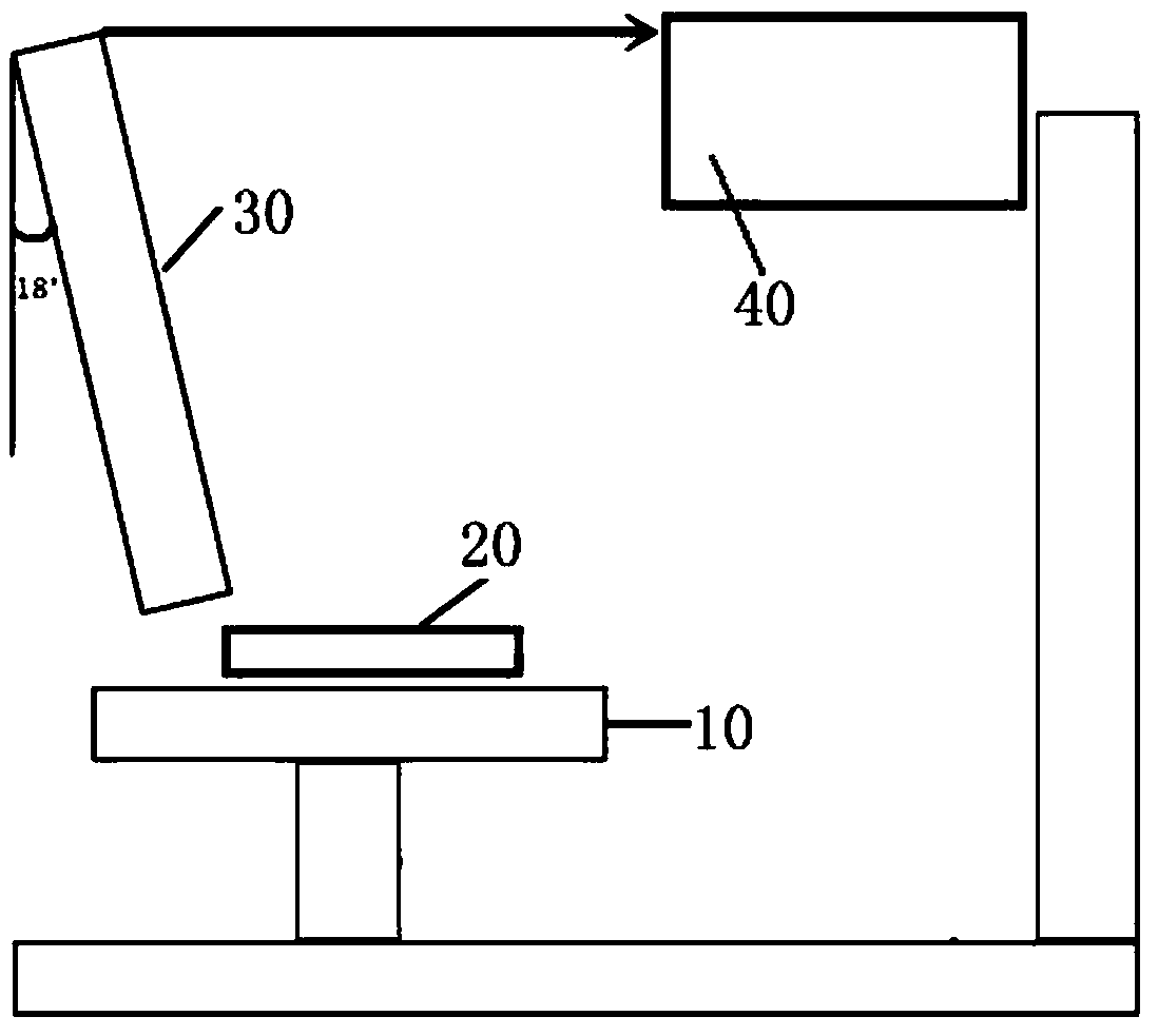
[0027] see figure 1 , as shown in the legend therein, a touch screen defect detection device based on a grayscale image and a height image includes a stage 10, an image acquisition device, an image generation device, an image processing device, and a data analysis device. The stage 10 carries the detected touch screen 20,

[0028] The image acquisition device is a line confocal camera, which collects coordinates, gray values ​​and height values ​​of each position of the detected touch screen 20 and forms a two-dimensional array;

[0029] The image generation device generates a grayscale image and a height image of the detected touch screen according to the two-dimensional array;

[0030] The image processing device performs defect extraction and size calculation on the grayscale image and the height image;

[0031] The data analysis equipment judges whether the ...


PUM


Abstract

The invention discloses a grey-scale map and height map based defect detecting device for a touch screen. The defect detecting device comprises a bearing platform, an image collecting apparatus, an image generating apparatus, an image processing apparatus and a data analyzing apparatus, wherein the bearing platform is used for bearing a to-be-detected touch screen; the image collecting apparatus is a linear confocal camera; the linear confocal camera is used for collecting the coordinates, gray-scale value and height value of each position of the to-be-detected touch screen and forming a two-dimensional array; the image generating apparatus is used for generating a grey-scale map and a height map of the to-be-detected touch screen according to the two-dimensional array; the image processing apparatus is used for carrying out defect extraction and size calculation on the grey-scale map and the height map; and the data analyzing apparatus is used for judging whether the to-be-detected touch screen is qualified or not according to the quantity and sizes of defects. According to the defect detecting device, the extraction of the grey-scale value is carried out on position information and grey-scale information reflected by the defects on the grey-scale map; the extraction is carried out on the heights of the defects reflected on the height image; and under such a double extractiontechnique, the higher accuracy can be guaranteed and moreover the detection requirement of a manufacturer can be met.

Description

technical field [0001] The invention relates to the field of product inspection, in particular to a touch screen defect inspection device based on a line confocal camera. Background technique [0002] Defect detection usually refers to the detection of surface defects of objects. Surface defect detection uses advanced machine vision detection technology to detect spots, pits, scratches, color differences, defects and other defects on the surface of workpieces. Defect detection technology has always been the detection However, there is no perfect solution in the market at present. Due to the high technical requirements for defect detection, and the extremely high requirements for missed and false positive rates required by manufacturers, defect detection has always been a headache. problem. [0003] At present, the scanning equipment in the market is mainly line-scan and area-scan cameras and 3D laser scanning equipment. For defect detection, line-scan and area-scan cameras ...

Claims


Application Information

Patent Timeline
IPC IPC(8): G01N21/88G01N21/01
CPCG01N21/01G01N21/8851G01N2021/0112G01N2021/8887
Inventor 姚钦刘天成陈晨
Owner SUZHOU DINNAR TECH FOR AUTOMATION CO LTD
Learn More