Method for determining compensation voltage of full compensation of grounding current of controllable voltage source

A technology for compensating voltage and ground current, applied in the direction of measuring electricity, measuring electrical variables, measuring devices, etc., can solve problems such as difficult application of distribution network system, complicated determination method of compensation voltage, etc., and achieve the effect of fast calculation method

Active Publication Date: 2019-03-26
YUNNAN POWER GRID CO LTD ELECTRIC POWER RES INST
View PDF6 Cites 13 Cited by
  • Summary
  • Abstract
  • Description
  • Claims
  • Application Information

AI Technical Summary

Problems solved by technology

[0003] This application provides a compensation voltage determination method for full compensation of the ground current of a controllable voltage source to solve the problem that the existing compensation voltage determination method for full current compensation is complicated and difficult to apply to the actual distribution network system

Method used


Image

  • Method for determining compensation voltage of full compensation of grounding current of controllable voltage source
  • Method for determining compensation voltage of full compensation of grounding current of controllable voltage source
  • Method for determining compensation voltage of full compensation of grounding current of controllable voltage source

Examples


Embodiment Construction

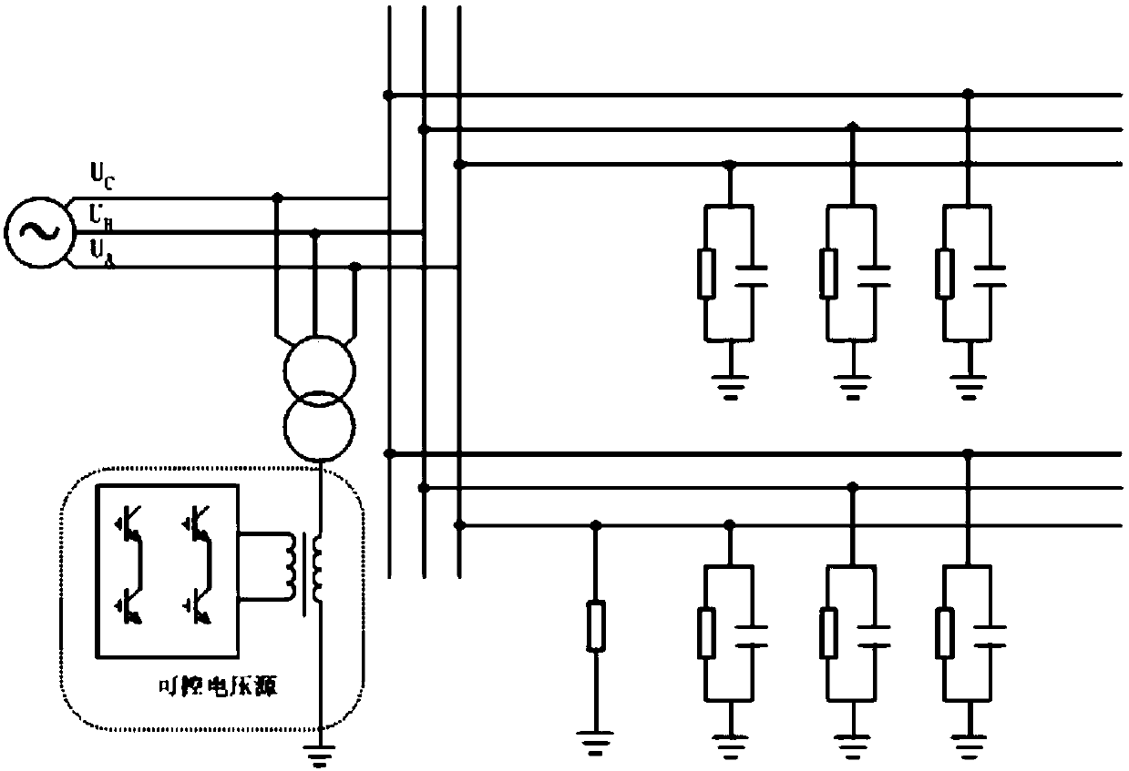
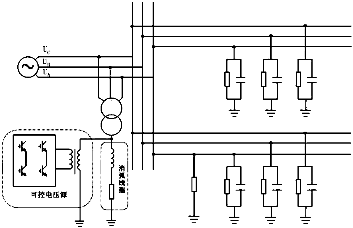
[0022] see figure 1 , the application provides a compensation voltage determination method for full compensation of the ground current of a controllable voltage source, which is applied to the ground fault current compensation of the distribution network using a controllable voltage source, and the specific circuit includes a controllable voltage source, a transformer and A three-phase power supply, the controllable voltage source is connected to the three-phase power supply through a transformer. Preferably, the controllable voltage source is connected in parallel with an arc suppression coil, and the specific circuit can be found in figure 2 , where U A , U B and U C Phases A, B and C of the three-phase voltage.

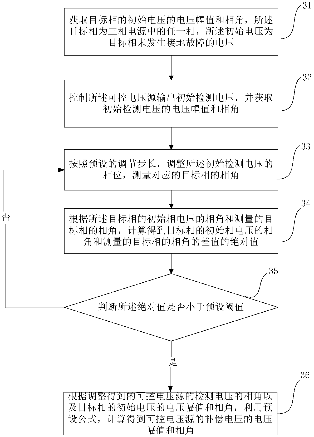
[0023] see image 3 , another embodiment of the present application provides a compensation voltage determination method for full compensation of the ground current of a controllable voltage source based on the above circuit, including the following steps:

...


PUM


Abstract

The invention provides a method for determining a compensation voltage for full compensation of the grounding current of a controllable voltage source. The method comprises steps that a voltage amplitude and a phase angle of an initial voltage of a target phase are acquired; the controllable voltage source is controlled for outputting an initial detection voltage, and a voltage amplitude and a phase angle of the initial detection voltage are acquired; the phase of the initial detection voltage is adjusted, and a corresponding phase angle of the target phase is measured; an absolute value of difference between the phase angle of the initial phase voltage of the target phase and the measured phase angle of the target phase is calculated; whether the absolute value is less than a preset threshold is determined, if yes, a voltage amplitude and a phase angle of a compensation voltage of the controllable voltage source are calculated and obtained, if not, the progress jumps to the step of adjusting the phase of the initial detection voltage. The method is advantaged in that under various topologies for full compensation of the grounding current of the controllable voltage source, a compensation output value of the controllable voltage source in single-phase grounding connection can be calculated quickly and accurately, the calculation method is fast, effective and simple, and the method can be well applied to a practical distribution network system.

Description

technical field [0001] The present application relates to the technical field of power grid single-phase ground full compensation, in particular to a compensation voltage determination method for full compensation of ground current of a controllable voltage source. Background technique [0002] In the power grid system, especially in the medium and low voltage distribution network system, the single-phase ground fault accounts for the absolute majority of the total number of faults. The neutral point grounding methods of the medium and low voltage distribution network mainly include the neutral point non-grounding method, the neutral point grounding method through the arc suppression coil or the neutral point grounding method through a low-value resistance. In the neutral point ungrounded mode, the ground current is not compensated and operates with a fault, which poses a risk of personal electric shock. When the neutral point is grounded through the arc-suppression coil, t...

Claims


Application Information

Patent Timeline
Patent Type & Authority Applications(China)
IPC IPC(8): G01R31/02G01R31/08
CPCG01R31/086G01R31/088G01R31/50
Inventor 刘红文王科
Owner YUNNAN POWER GRID CO LTD ELECTRIC POWER RES INST
Why Eureka
Try Eureka