
Electrochromic device with shoulder-to-shoulder structure and application thereof

An electrochromic device and electrochromic technology, applied in instruments, nonlinear optics, optics, etc., can solve problems such as complex preparation process, high cost, difficulty in device integration and flexible design, and expand the range of options , The structure of the device is simple, and the effect of improving the integration degree

Pending Publication Date: 2019-03-26
WUYI UNIV
View PDF0 Cites 6 Cited by
  • Summary
  • Abstract
  • Description
  • Claims
  • Application Information

AI Technical Summary

Problems solved by technology

[0004] However, in traditional electrochromic devices, the injection and extraction of cations are carried out in the vertical direction, and the ion storage layer and the color-changing layer are respectively located on different functional layers in the vertical direction, so the colors and positions of the two must match to be able to The color-changing layer can display its own color or color change, which limits the diversification and personalized design of electrochromic device colors to a large extent, and is not easy to integrate and flexibly design the device
In addition, the complex preparation process and high cost of traditional electrochromic devices have greatly affected the wide-scale commercial application of electrochromic devices.

Method used


Image

  • Electrochromic device with shoulder-to-shoulder structure and application thereof
  • Electrochromic device with shoulder-to-shoulder structure and application thereof
  • Electrochromic device with shoulder-to-shoulder structure and application thereof

Examples


Embodiment 1

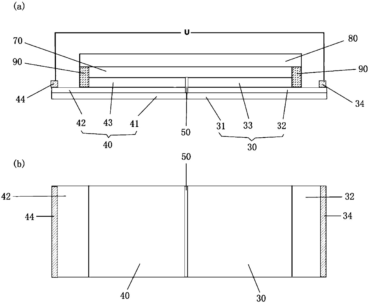
[0046] see figure 1 , which is a schematic diagram of an electrochromic device with a side-by-side structure in this embodiment, wherein figure 1 (a) is the front view of the electrochromic device of the side by side structure of the present embodiment, figure 1 (b) is a top view of the side-by-side electrochromic device of this embodiment.

[0047] The side-by-side electrochromic device of this embodiment includes a common electrode unit 40 , a color-changing unit 30 , an electrolyte layer 70 , a transparent encapsulation layer 80 and an adhesive 90 .

[0048] The common electrode unit 40 includes a substrate 41, an electrode layer 42 completely covering the substrate 41, and an electrode protection layer 43 disposed on the electrode layer 42, and is connected to the electrode protection layer 43 and the color-changing layer. 33. And the electrode protection layer 43 covers one side of the electrode layer 42 , and the lead electrode 44 is provided on the uncovered area of ...

Embodiment 2

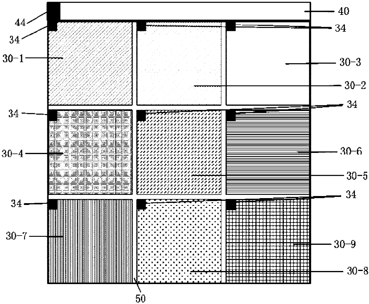
[0065] see image 3 , which is a top view of the side-by-side electrochromic device of this embodiment.

[0066] The side-by-side electrochromic device of this embodiment includes a common electrode unit 40, 9 color-changing units, an electrolyte layer, a transparent encapsulation layer and an adhesive. The nine discoloration units are discoloration unit 30-1, discoloration unit 30-2, discoloration unit 30-3, discoloration unit 30-4, discoloration unit 30-5, discoloration unit 30-6, discoloration unit 30-7, Color changing unit 30-8 and color changing unit 30-9.

[0067] The common electrode unit 40 includes a rectangular substrate, an electrode layer completely covering the substrate, and an electrode protection layer disposed on the electrode layer, and the electrode protection layer partially covers the electrode layer On the electrode layer, leave an uncovered area at one end of the electrode layer, on which a lead electrode 44 is provided.

[0068] Each color-changing u...

Embodiment 3

[0085] see Figure 5 , which is a top view of the side-by-side electrochromic device of this embodiment.

[0086] The side-by-side electrochromic device of this embodiment includes a common electrode unit 40, two color-changing units, an electrolyte layer, a transparent encapsulation layer and an adhesive. The two color changing units are respectively a color changing unit 30-1 and a color changing unit 30-2.

[0087] The common electrode unit 40 includes a rectangular substrate, an electrode layer completely covering the substrate, and an electrode protection layer 43 disposed on the electrode layer, and the electrode protection layer 43 covers the electrode layer Above the middle part of one side, an uncovered area surrounding the electrode protection layer 43 is left, and a lead electrode 44 is provided in the middle of the uncovered area.

[0088] Each color-changing unit includes a rectangular transparent substrate, a transparent conductive layer completely covering the...


PUM


Abstract

The invention relates to an electrochromic device with a shoulder-to-shoulder structure. The electrochromic device comprises a common electrode unit, at least one color changing unit and an electrolyte layer, wherein the common electrode unit includes an electrode layer and an electrode protection layer arranged on the electrode layer, each color changing unit includes a transparent conductive layer and a color changing layer arranged on the transparent conductive layer, the common electrode unit and each color changing unit are arranged on the same plane, two adjacent units are provided withan insulating area therebetween, and the electrolyte layer covers the electrode protection layer in the common electrode unit and the color changing layer in each color changing unit and connects theelectrode protection layer in the common electrode unit and the color changing layer in each color changing unit. According to the invention, an electrochromic device with a sandwich structure is flattened into the electrochromic device with a shoulder-to-shoulder structure, thereby being conducive to realizing multi-color and personalized pattern design of the electrochromic device, and reducingthe difficulty of integration, softening and large-area design.

Description

technical field [0001] The invention relates to the field of electrochromic and electronic display, in particular to a side-by-side electrochromic device and its application. Background technique [0002] Electrochromic materials are smart materials that can undergo stable and reversible color changes under external electrical stimulation and have optical modulation capabilities. With the electrochromic material as the core layer, matching the corresponding electrolyte layer and the counter electrode layer can be assembled to obtain a sandwich-structured electrochromic device, which can be applied to assembly windows (also called smart windows), displays, file encryption and Color-changing glasses and other fields. [0003] The traditional electrochromic device is a sandwich structure similar to a battery integrated with a variety of materials, including a five-layer structure composed of a transparent conductive layer, an ion storage layer, an electrochromic layer and an e...

Claims


Application Information

Patent Timeline
IPC IPC(8): G02F1/153G02F1/155
CPCG02F1/153G02F1/155G02F2001/1557G02F1/1525
Inventor 唐秀凤陈国新李泳贤李智信莫钊鹏区芷君黄腾程苏澜张泽辉罗坚义
Owner WUYI UNIV
Learn More