Inner-cooling composite rotating direction dry type cutting milling cutter

A dry cutting and milling cutter technology, applied in the direction of milling cutters, milling machine equipment, manufacturing tools, etc., can solve the problems of poor surface finish, low processing efficiency, and poor heat dissipation effect of the processed workpiece, so as to suppress the generation of built-up edge and eliminate Chips are smooth and easy to dissipate heat

Pending Publication Date: 2019-03-29
江苏戴梦德钻石科技有限公司
View PDF0 Cites 0 Cited by
  • Summary
  • Abstract
  • Description
  • Claims
  • Application Information

AI Technical Summary

Problems solved by technology

[0003] The technical problem to be solved by the present invention is: in order to solve the technical problems of poor heat dissipation effect of cutting tools, poor surface finish of processed workpiece and low processing efficiency in the prior art, the present invention provides an internal cooling composite rotary dry cutting milling cutter to solve the above problems

Method used


Image

  • Inner-cooling composite rotating direction dry type cutting milling cutter
  • Inner-cooling composite rotating direction dry type cutting milling cutter
  • Inner-cooling composite rotating direction dry type cutting milling cutter

Examples


Embodiment 1

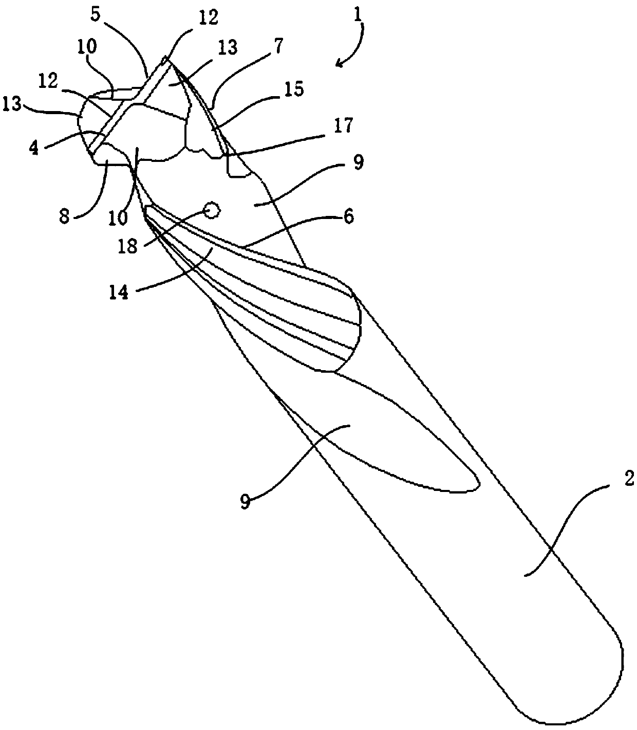
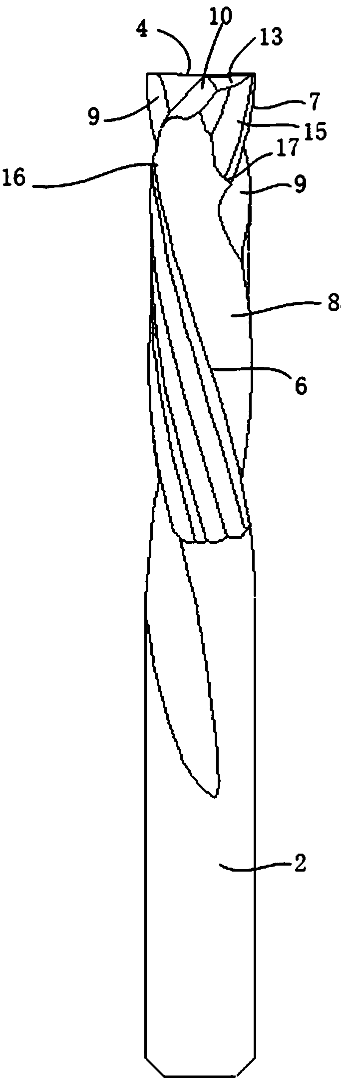
[0030] Example 1, such as Figure 1-3 As shown, a kind of internal cooling composite rotary dry cutting milling cutter is used for processing flat bottom grooves, including a cutter head 1 and a handle 2 made of hard alloy, the diameter of the handle 2 is 6mm, and the cutter head 1 is composed of two Each cutting seat 3 consists of an end edge, a right-handed right cutting edge 7 and a left-handed right edge 6. The end edge is a straight edge with a blade inclination angle of 2°, which is used for cutting the bottom of a plane hole, and the end edge There is an end tooth chip pocket 10 in front of the edge for chip removal at the end, and two end edge flanks are arranged behind the end edge, including an end edge flank 12 and an end edge rear flank arranged in sequence behind the end edge. Cutter face two 13, the relief angle of end edge flank one 12 is 12°, and the relief angle of end edge flank two 13 is 22°; The front of the right-handed cutting edge 7 is provided with a r...

Embodiment 2

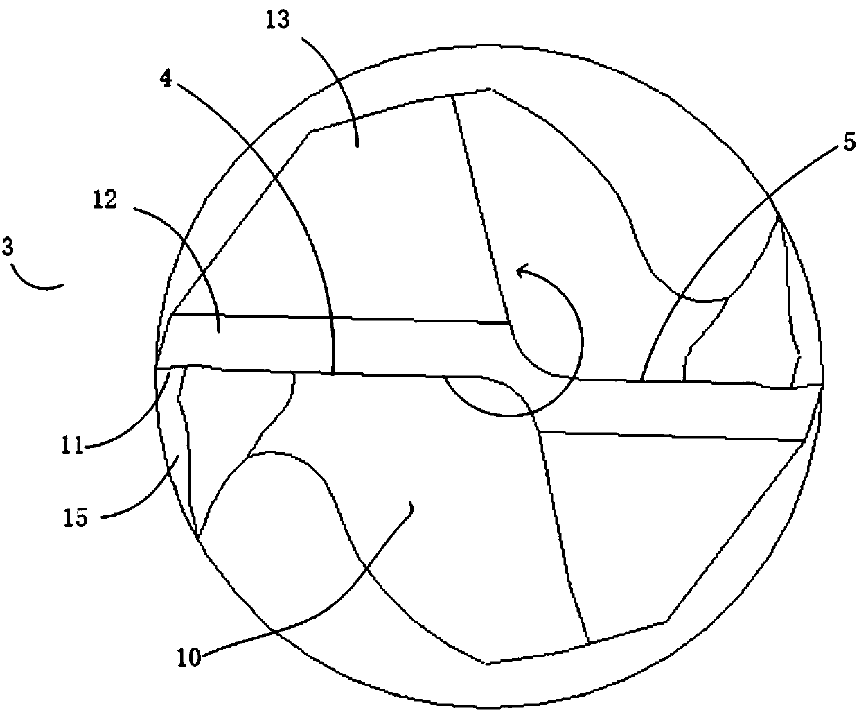
[0032] Embodiment 2, since the cutter head 1 is provided with two end edges, in order to avoid chip accumulation in the center of the hole bottom surface, such as image 3 As shown, on the basis of Embodiment 1, the lengths of the end edges of the two cutting seats 3 in this embodiment are different, which are respectively the long end edge 4 and the short end edge 5, and the long end edge 4 and the short end edge 5 along the cutting edge The end face of 1 is radially arranged in parallel, and the end point of the long end edge 4 passes through the center of the end face of the cutter head 1, so that the cutting plane of the long end edge 4 and the short end edge 5 can cover the entire hole bottom surface, and the long end edge 4 and the short end edge The end edges 5 do not intersect, so that the chip removal of the two end edges is broken. Specifically, the length of the end point of the long end edge 4 through the center of the end face of the cutter head 1 is 0.2 mm.

Embodiment 3

[0033] Embodiment 3, because the stress at the starting point of cutting is relatively large, in order to increase the sharpness of the cutting edge, such as image 3As shown, in this embodiment, on the basis of embodiment 1 or embodiment 2, the right-handed chip flute 9 intersects with the end edge to form a crescent secondary edge 11 .


PUM


Abstract

The invention discloses an inner-cooling composite rotating direction dry type cutting milling cutter. The inner-cooling composite rotating direction dry type cutting milling cutter comprises a cutterbit and a cutter handle. The cutter bit is composed of two cutting bases. Each cutting base comprises an end blade, a rightward rotating and cutting side blade and a leftward rotating and rightward cutting side blade. End tooth chip pockets are arranged in front of the end blades, and end blade rear cutter faces are arranged behind the end blades. The starting points of the rightward rotating andcutting side blades are connected with the end blades, rightward rotating chip discharge grooves are formed in front of the right rotating and cutting side blades, and right rotating side blade rearcutter faces are arranged behind the right rotating and cutting side blades. Leftward rotating chip discharge grooves are formed in front of the leftward rotating and rightward cutting side blades, and the leftward rotating chip discharge grooves and the rightward rotating chip discharge grooves intersect to form the starting points of the leftward rotating and rightward cutting side blades. Leftward rotating side blade rear cutter faces are arranged behind the leftward rotating and rightward cutting side blades. The inner-cooling composite rotating direction dry type cutting milling cutter can be used for machining key grooves of mobile phones and tablet computers made of aluminum-plastic composites, the surface smoothness of machined products is good, and burrs generated during machiningare reduced.

Description

technical field [0001] The invention relates to the technical field of mechanical manufacturing and cutting processing, in particular to an inner-cooling composite rotary dry cutting milling cutter. Background technique [0002] A milling cutter is a rotating tool with one or more teeth for milling operations. When working, each knife tooth cuts off the allowance of the workpiece intermittently in turn. Due to its composite nature, aluminum-plastic materials cause different edge wear, poor processing finish, and low processing efficiency during conventional tool processing. Mobile phones are mainly made of aluminum-plastic composite materials. Button-type mobile phones need to process many key slots. The process is smooth, and the surface of the body is smooth after the key is installed. The keyway needs to have a good surface finish and requires high machining accuracy. In addition, during the dry cutting process, the chip removal temperature is too high. The previous cut...

Claims


Application Information

Patent Timeline
Patent Type & Authority Applications(China)
IPC IPC(8): B23C5/10B23C5/28
CPCB23C5/10B23C5/28
Inventor 祁光华鄂胜林祁伟黄飞
Owner 江苏戴梦德钻石科技有限公司
Why Eureka
Try Eureka