Tank body welding robot

A technology for welding robots and tanks, which is applied in welding equipment, welding equipment, auxiliary welding equipment, etc., can solve problems such as difficult to realize automatic welding of circular seams and straight seams, and achieve simple and convenient lifting and handling, convenient handling, and welding process Simple and convenient effect

Pending Publication Date: 2019-03-29
WUHAN ENG SCI & TECH RESINST +1
View PDF1 Cites 5 Cited by
  • Summary
  • Abstract
  • Description
  • Claims
  • Application Information

AI Technical Summary

Problems solved by technology

[0002] At present, in the welding process of some tank bodies, the automatic welding of the welding positioner is usually used for the girth welding of the tank body. The automatic welding has made great progress in solving the quality and efficiency of manual welding, but for some larger Tank body, it is difficult to realize automatic welding of circular seam and straight seam with welding positioner

Method used


Image

  • Tank body welding robot
  • Tank body welding robot
  • Tank body welding robot

Examples


Embodiment 1

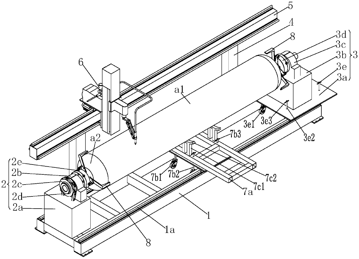
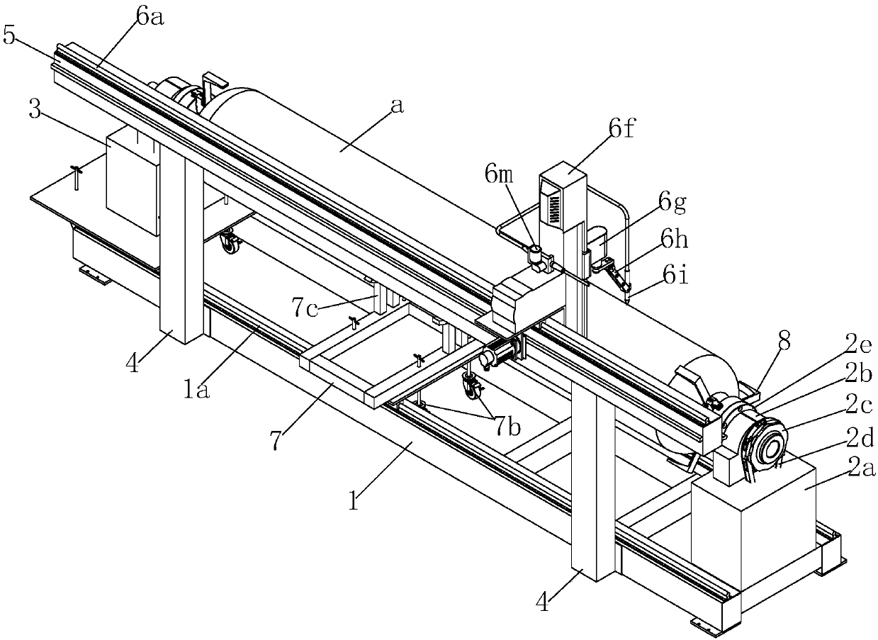
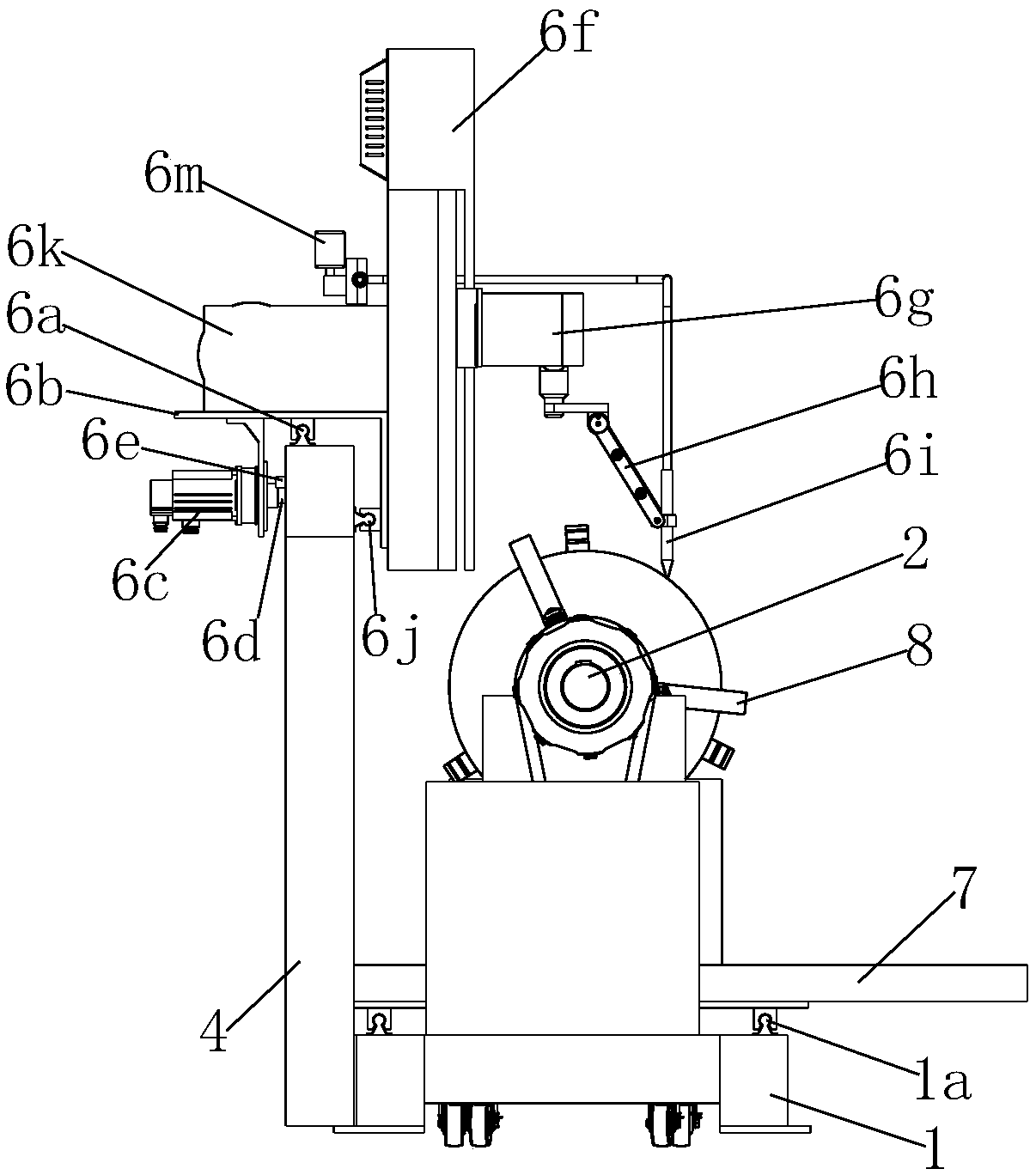
[0041] Such as figure 1 As shown, a tank body welding robot provided in this embodiment includes a base 1, and one end of the base 1 is fixedly installed with a tank body support drive assembly 2, and the tank body support drive assembly 2 includes a tank body support drive assembly fixedly installed on the The first support platform 2a on the base 1, the three-jaw chuck driving motor is installed in the first support platform 2a, the first bearing seat 2b is arranged on the top surface of the first support platform 2a, the first A first rotating shaft is installed in the bearing seat 2b, and a driving sprocket 2c is installed on one end of the first rotating shaft, and the driving sprocket 2c is connected to the output end of the three-jaw chuck driving motor through a driving chain 2d. The other end of the first rotating shaft is equipped with a first three-jaw chuck 2e; the two sides of the base 1 are respectively equipped with a base guide rail 1a, and the other end of the...

Embodiment 2

[0055] Such as figure 1 As shown, the welding method of a tank body welding robot provided in this embodiment includes the following steps:

[0056] (1) A tank body a1 is spot-welded with two tank bottoms a2 to obtain a tank body a to be welded;

[0057] (2) clamping the tank body a to be welded between the first three-jaw chuck 2e and the second three-jaw chuck 3d;

[0058] (3) Adjust the welding torch 6i to the seam position between the tank body a1 and the tank bottom a2;

[0059] (4) Rotate the first three-jaw chuck 2e to drive the tank body a to be welded to rotate together, and the welding torch 6i completes the welding between the tank body a1 and a tank bottom a2;

[0060] (5) Turn the first three-jaw chuck 2e to adjust the position of the seam on the can body a1, and adjust the position of the welding torch 6i so that the welding torch 6i is aligned with the seam on the can body a1 Patchwork;

[0061](6) The X-axis drive motor 6c drives the welding torch 6i to mov...


PUM


Abstract

The invention discloses a tank body welding robot. The tank body welding robot comprises a base, wherein a tank body support driving assembly is arranged at one end of the base; base guide rails are arranged on the two sides of the base, a tank body supporting assembly is arranged at the other end of the base, the tank body supporting assembly comprises a supporting table bottom plate arranged onthe base guide rails and a second supporting table arranged on the supporting table bottom plate, a second bearing block is arranged on the second supporting table, and a second rotating shaft with asecond three-jaw chuck is arranged in the second bearing block; an X-axis cross beam is arranged on one side of the base, a welding assembly is arranged on the X-axis cross beam, the welding assemblycomprises a top surface X-axis guide rail, the top surface X-axis guide rail is laid on the top surface of the X-axis cross beam, an X-axis rack is laid on the outer side surface of the X-axis cross beam, and an L-shaped sliding plate cross arm is arranged on the top surface X-axis guide rail; and an X-axis driving motor with an X-axis driving gear is arranged on the L-shaped sliding plate cross arm, a Z-axis electric sliding table is arranged on the L-shaped sliding plate, a welding gun mounting base is arranged on a sliding table sliding block, a position fine adjusting assembly is arrangedon the welding gun mounting base, and the position fine adjusting assembly is provided with a welding gun. The tank body welding robot is suitable for welding of the tank body.

Description

technical field [0001] The invention relates to the welding field, in particular to a tank body welding robot. Background technique [0002] At present, in the welding process of some tank bodies, the automatic welding of the welding positioner is usually used for the girth welding of the tank body. The automatic welding has made great progress in solving the quality and efficiency of manual welding, but for some larger For the tank body, it is difficult to realize the automatic welding of circular seam and straight seam by welding positioner. Contents of the invention [0003] The object of the present invention is to provide a tank body welding robot in order to overcome the above-mentioned deficiencies in the background technology. [0004] In order to achieve the above object, a tank body welding robot provided by the present invention includes a base, one end of the base is fixedly installed with a tank body support drive assembly, and the tank body support drive ass...

Claims


Application Information

Patent Timeline
Patent Type & Authority Applications(China)
IPC IPC(8): B23K31/02B23K37/047B23K37/053B23K37/02B23K37/00
CPCB23K31/02B23K37/00B23K37/0211B23K37/047B23K37/053
Inventor 陈和平阿庆宇宋丹江晟黄荣腾王晓晖
Owner WUHAN ENG SCI & TECH RESINST
Why Eureka
Try Eureka