Differential mechanism housing surface polishing equipment

A surface polishing and differential technology, which is applied in the direction of grinding/polishing equipment, surface polishing machine tools, metal processing equipment, etc., can solve the problem of discounting the life and utilization rate of the differential housing, ineffective removal of burrs, and differential Polishing of the device shell and other issues to achieve the effect of increasing motion activity, improving polishing quality, and reducing damage

Inactive Publication Date: 2019-03-29
YUEXI COUNTY HONGSHENG CASTING
View PDF11 Cites 5 Cited by
  • Summary
  • Abstract
  • Description
  • Claims
  • Application Information

AI Technical Summary

Problems solved by technology

The differential housing is generally welded by the combination of the left and right housings. The joint surface will inevitably have some burrs, which need to be polished, but the traditional polishing machine is difficult to achieve Reasonable, multi-directional polishing of the differential case, uneven polishing work, can not effectively remove burrs, so that the life and utilization rate of the differential case will be greatly reduced

Method used


Image

  • Differential mechanism housing surface polishing equipment
  • Differential mechanism housing surface polishing equipment
  • Differential mechanism housing surface polishing equipment

Examples


Embodiment 1

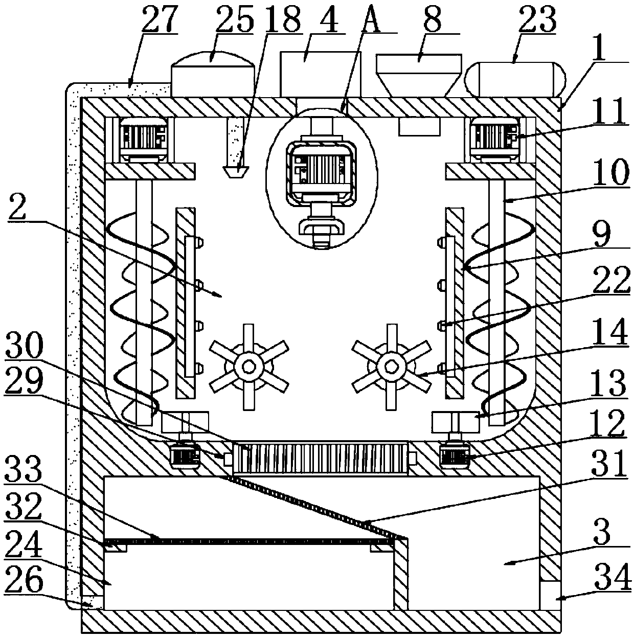
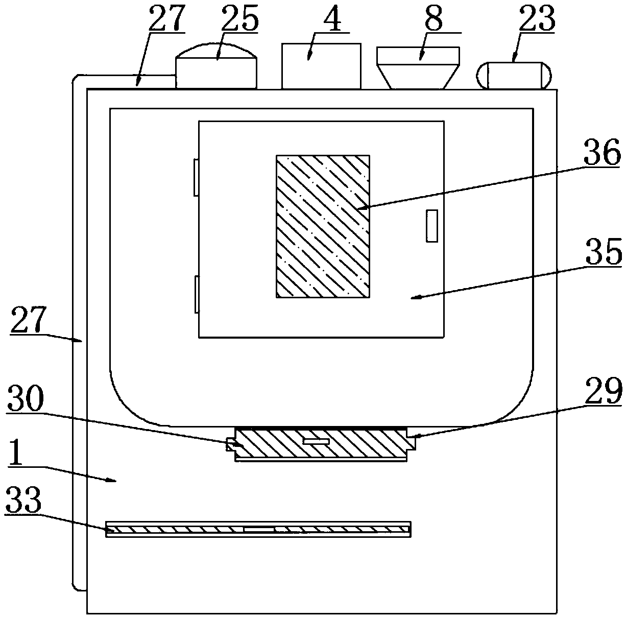
[0026] according to figure 1 and 5 The surface polishing equipment for a differential case shown includes a box body 1, a polishing chamber 2 is provided inside the box body 1, a silo 3 is provided at the bottom of the polishing chamber 2, and a silo 3 is provided at the top center of the polishing chamber 2. There is a cylinder 4, the output end of the cylinder 4 is fixedly connected with a housing 5, the inside of the housing 5 is fixedly connected with a first motor 6, the output shaft of the first motor 6 is fixedly connected with a connecting sleeve 7, and the cylinder 4 One side is provided with a feed port 8, and both sides of the polishing chamber 2 are provided with arc-shaped plates 9, and a lifting cavity is provided between the curved plate 9 and the inner wall of the box body 1, and the lifting cavity is provided with A screw rod 10, the top of the screw rod 10 is provided with a second motor 11, the output shaft of the second motor 11 is in transmission connecti...

Embodiment 2

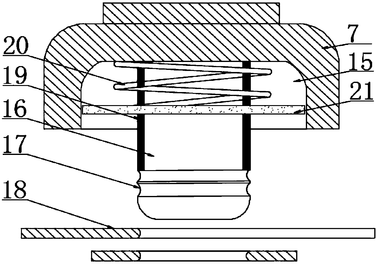
[0029] according to Figure 3-4 In the shown surface polishing equipment for a differential case, a groove 15 is provided at the bottom of the connecting sleeve 7, and an insertion rod 16 is fixedly connected to the center of the groove 15, and two bottom ends of the insertion rod 16 are provided. Parallel arc-shaped grooves 17, two arc-shaped grooves 17 are provided with vertically distributed U-shaped clamping plates 18, and the inside of the U-shaped clamping plate 18 is provided with a convex arc that matches the arc-shaped grooves 17, By inserting the inserting rod 16 into the through pipe at the top of the differential case and using two U-shaped clamping plates 18 to intersect the inside of the two arc-shaped grooves 17, the differential case can be fixedly installed, which is convenient, quick and easy to operate , which is conducive to improving the processing efficiency;

[0030] The outer side of the insertion rod 16 is provided with a buffer pad 19, the outer side...


PUM


Abstract

The invention discloses differential mechanism housing surface polishing equipment which comprises a box body, wherein a polishing chamber is formed in the box body; a stock bin is arranged at the bottom of the polishing chamber; an air cylinder is arranged at the top center of the polishing chamber; a housing is fixedly connected with the output end of the air cylinder; a first motor is fixedly connected with the interior of the housing; and a connecting sleeve is fixedly connected with the output shaft of the first motor. According to the differential mechanism housing surface polishing equipment, the differential mechanism housing is fixedly mounted through the connecting sleeve to adjust the length of the output end of the air cylinder, the output end of the first motor is in transmission connection with the connecting sleeve to rotate the differential mechanism housing in polishing sand, a third motor is in transmission connection with a guiding wheel to enable the polishing sandto enter a lifting cavity from a channel, the output end of a second motor is in transmission connection with a screw rod, the screw rod lifts the polishing sand up, the polishing sand sprays out of an upper channel to act on the top of the differential mechanism housing, and the motors are in in transmission connection with gears to enable two stirring wheels to rotate relatively so as to improvethe moving activity of the polishing sand, so that reasonable and multidirectional polishing on the differential mechanism housing is realized and the polishing quality is improved.

Description

technical field [0001] The invention relates to the field of component polishing equipment, in particular to a surface polishing equipment for a differential case. Background technique [0002] The differential is a very important part of an electric vehicle. It is a mechanism that enables the left and right or front and rear drive wheels to rotate at different speeds. It is mainly composed of left and right side shaft gears, two planetary gears and a gear rack. Its function is to drive the car when turning. Or when driving on uneven roads, make the left and right wheels roll at different speeds, that is, to ensure the pure rolling motion of the driving wheels on both sides, and the differential is installed to adjust the speed difference between the left and right wheels, so the differential is a kind of Parts that require high precision. The differential housing is generally welded by the combination of the left and right parts of the housing, and the joint surface will i...

Claims


Application Information

Patent Timeline
Patent Type & Authority Applications(China)
IPC IPC(8): B24B31/10B24B31/12B24B47/12B24B55/06
CPCB24B31/10B24B31/12B24B47/12B24B55/06
Inventor 刘扬兵
Owner YUEXI COUNTY HONGSHENG CASTING
Why Eureka
Try Eureka