
Automatic clamping device and method for diode lead

A diode and lead technology is applied in the field of diode lead automatic clamping devices, which can solve the problems of low work efficiency and high labor intensity, and achieve the effects of convenient operation, reduced labor intensity and strong practicability.

Pending Publication Date: 2019-03-29
GUIZHOU YAGUANG ELECTRONICS TECH
View PDF8 Cites 0 Cited by
  • Summary
  • Abstract
  • Description
  • Claims
  • Application Information

AI Technical Summary

Problems solved by technology

At present, in the production process of diodes, it is necessary to place the diodes in a baking tray for drying treatment, but at present, they are all manually loaded into the trays. This method has problems such as high labor intensity and low work efficiency.

Method used


Image

  • Automatic clamping device and method for diode lead
  • Automatic clamping device and method for diode lead

Examples


Embodiment Construction

[0019] Below in conjunction with accompanying drawing and specific embodiment the invention is further introduced:

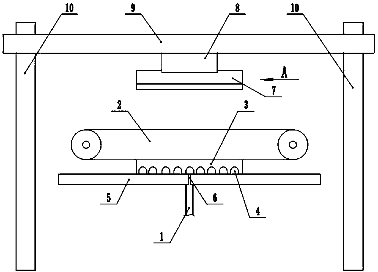
[0020] see figure 1 , according to the present invention, a diode lead automatic clamping device, including a vibrating feeder, feed channel 1, bar-shaped straight plate 5, diode stacking plate 3, circulation conveying mechanism 2, diode pick-up clip 7 and three-dimensional moving mechanism.

[0021] The vibrating feeder is a commonly used device in the field of diode production. Its function is to arrange the diodes in such a way that the leads face upward and the base is downward after vibration, and output them sequentially from the discharge channel. The discharge channel of the vibrating feeder is communicated with the feed channel 1, so that the diode can be input into the feed channel 1 with the lead wire facing up and the base down.

[0022] The strip-shaped straight plate 5 has a transition channel 6 communicating with the feed channel 1 . Preferably,...


PUM


Abstract

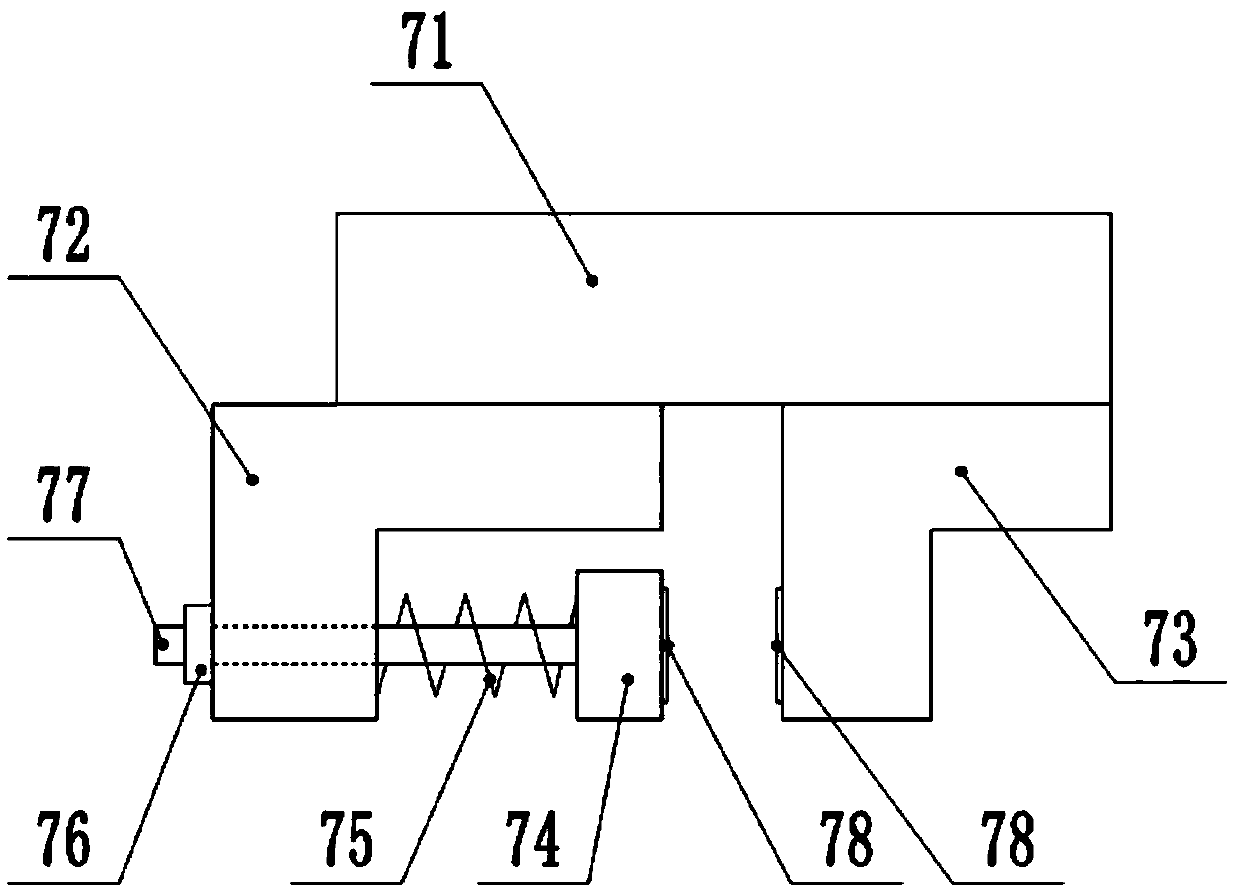
The invention discloses an automatic clamping device and method for a diode lead. The automatic clamping device comprises a feeding channel, a strip-shaped straight plate, a diode stacking plate, a circulating conveying mechanism and a three-dimensional moving mechanism, wherein the strip-shaped straight plate is provided with a transition channel which communicates with the feeding channel; one side of the diode stacking plate is provided with a plurality of opening stacking slots for stacking didoes in a spaced mode in a length direction; the diode stacking plate can perform reciprocating movement relative to the strip-shaped straight plate, so that the opening stacking slots are sequentially aligned to the transition channel to receive diodes conveyed from the transition channel; the circulating conveying mechanism is used for driving the diode stacking plate; a diode take-up clamp comprises a fixed block and a slide block, and the slide block is connected onto a telescopic mechanism; the telescopic mechanism is used for driving the slide block to get close to or get away from the fixed block; and the three-dimensional moving mechanism is used for driving the diode take-up clampto move in a three-dimensional direction. Compared with a conventional manual loading way, the automatic clamping device greatly improves loading efficiency and reduces labour intensity.

Description

technical field [0001] The invention relates to an automatic clamping device for diode lead wires, which belongs to the technical field of diode feeding. Background technique [0002] Among electronic components, a diode is a device with two electrodes that only allows current to flow in one direction. Many uses apply its rectification function. The varactor diode is used as an electronic adjustable capacitor. The current directionality of most diodes is commonly referred to as the "rectification" function. The most common function of a diode is to only allow current to pass in a single direction (called forward bias), and to block it when it is reversed (called reverse bias). At present, in the production process of diodes, it is necessary to place the diodes in a baking tray for drying treatment, but at present, they are all manually loaded into the trays. This method has problems such as high labor intensity and low work efficiency. Contents of the invention [0003]...

Claims


Application Information

Patent Timeline
Patent Type & Authority Applications(China)
IPC IPC(8): B65B35/36B65B35/30B65B35/56
CPCB65B35/30B65B35/36B65B35/56
Inventor 陈林朱灿柴美荣
Owner GUIZHOU YAGUANG ELECTRONICS TECH
Learn More