
Ejector rocket for rocket-based combined cycle engine

A technology for ejecting rockets and engines, which is applied in the direction of rocket engine devices, machines/engines, mechanical equipment, etc., can solve the problems that active cooling is difficult to meet the thermal protection requirements, fuel is limited, etc., and achieve lower thermal protection requirements and high total pressure loss , the effect of large resistance

Active Publication Date: 2019-03-29
NAT UNIV OF DEFENSE TECH
View PDF7 Cites 8 Cited by
  • Summary
  • Abstract
  • Description
  • Claims
  • Application Information

AI Technical Summary

Problems solved by technology

However, due to the limited fuel carried by the aircraft, active cooling may be difficult to meet the thermal protection requirements when the flight Mach number is high or the nozzle surface area is large

Method used


Image

  • Ejector rocket for rocket-based combined cycle engine
  • Ejector rocket for rocket-based combined cycle engine
  • Ejector rocket for rocket-based combined cycle engine

Examples


Embodiment Construction

[0023] In order to make the object, technical solution and advantages of the present invention clearer, the present invention will be further described in detail below in conjunction with the accompanying drawings and embodiments. It should be understood that the specific embodiments described here are only used to explain the present invention, not to limit the present invention.

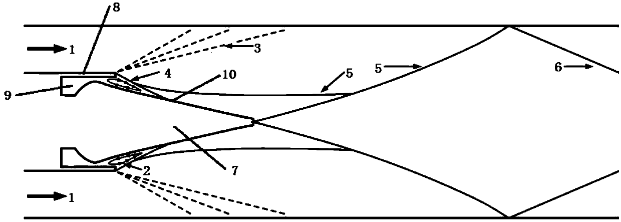
[0024] The invention provides an ejector rocket applied to a rocket-based combined cycle engine, which includes a nozzle, and the nozzle is a plug nozzle. The plug nozzle includes a central plug cone 7 and an outer wall 8 of the nozzle. The bottom end of the central plug cone 7 is set inside the outer wall 8 of the nozzle, and the tip of the central plug cone 7 extends out of the outer wall 8 of the nozzle. In this embodiment, the central plug cone 7 is a hollow plug cone. The outer wall 8 of the nozzle is a cylindrical structure with a rectangular cross-section, and its interior is a flow channel...


PUM


Abstract

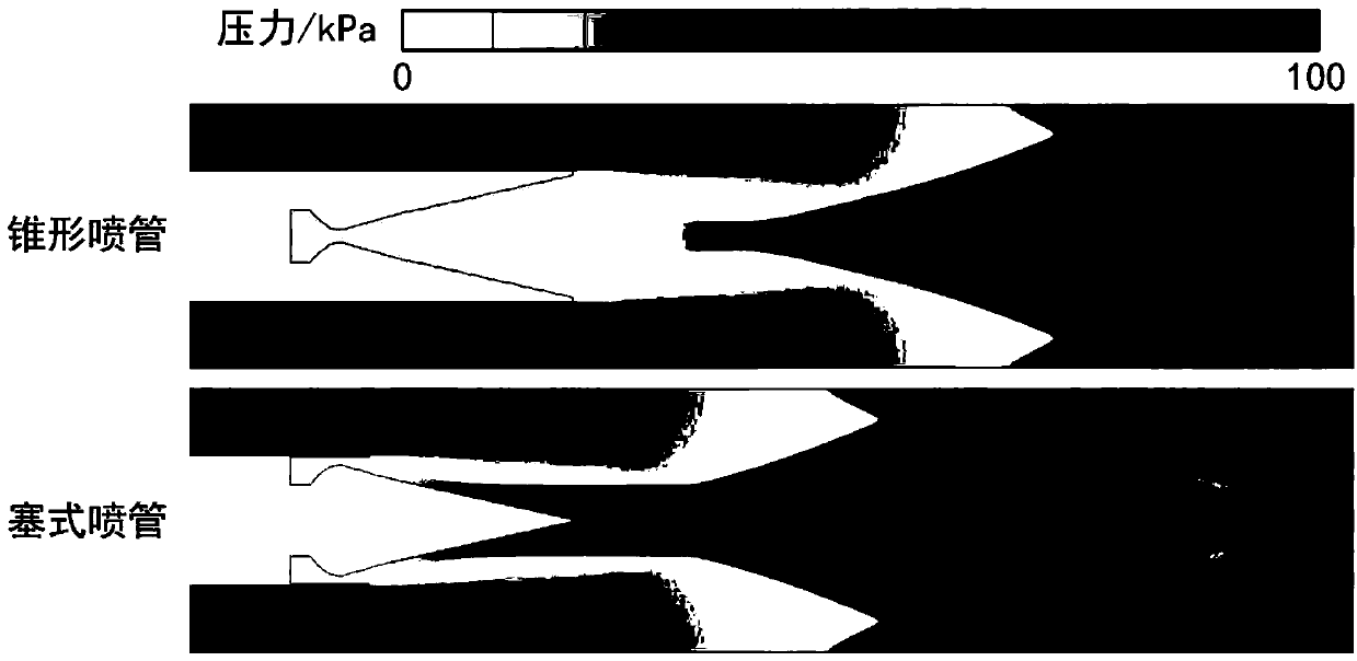
The invention provides an ejector rocket for rocket-based combined cycle engine. The ejector rocket includes a jet pipe. The jet pipe is a plug type jet pipe. According to the invention, in the ejector rocket, the plug type jet pipe is adopted instead of a conical or bell-shaped jet pipe in the prior art so as to improve the pressure at the bottom of the jet pipe of the ejector rocket in a stamping mode and reduce the bottom resistance. Therefore, a recirculation zone at the bottom of the ejector rocket is reduced and the total pressure loss is reduced. Meanwhile, in the stamping mode, the plug type jet pipe can reduce the area of a high temperature zone and reduce thermal protection requirements.

Description

technical field [0001] The invention relates to the technical field of rocket-based combined cycle engines, in particular to an ejector rocket applied to rocket-based combined cycle engines. Background technique [0002] At present, rocket based combined cycle (Rocket Based Combined Cycle, RBCC) engines mostly use ejector rockets with conical or bell-shaped nozzles. The ejection rocket is an important part of the rocket-based combined cycle engine, and it is the main source of engine thrust in the ejection mode (when the flight Mach number is less than 3). [0003] In order to ensure that sufficient power can be provided for the aircraft, the size of the launch rocket is relatively large, which can account for more than 40% of the total cross-sectional area of ​​the runner. However, as the flight Mach number increases, when the engine enters the ramming mode, it is necessary to turn off the ejector rocket to improve the overall specific impulse performance of the engine. ...

Claims


Application Information

Patent Timeline
IPC IPC(8): F02K1/38F02K1/78F02K9/97
CPCF02K1/38F02K1/78F02K9/97
Inventor 安彬孙明波杨雷超王振国陈健蔡尊董泽宇王泰宇匡孝波
Owner NAT UNIV OF DEFENSE TECH
Learn More