High bypass ratio turbofan engine and aero engine compression system

An aero-engine and compression system technology, which is applied to machines/engines, liquid fuel engines, mechanical equipment, etc., and can solve the problems of the fan and the turbocharger rotor speed being too high, increasing the quality of the engine, and poor boosting effect.

Inactive Publication Date: 2019-03-29
AECC COMML AIRCRAFT ENGINE CO LTD
View PDF8 Cites 2 Cited by
  • Summary
  • Abstract
  • Description
  • Claims
  • Application Information

AI Technical Summary

Problems solved by technology

[0005] Limited by the flow velocity at the tip of the fan blade, the rotor speed of the fan and the booster stage cannot be very high, which makes the boosting effect of the gas pass through the booster stage poor; if the

Method used


Image

  • High bypass ratio turbofan engine and aero engine compression system
  • High bypass ratio turbofan engine and aero engine compression system

Examples


Embodiment Construction

[0018] The present invention will be further described below in conjunction with specific embodiment and accompanying drawing, set forth more details in the following description so as to fully understand the present invention, but the present invention can obviously be implemented in many other ways different from this description, Those skilled in the art can make similar promotions and deductions based on actual application situations without violating the connotation of the present invention, so the content of this specific embodiment should not limit the protection scope of the present invention.

[0019] It should be noted that the drawings are only examples, and they are not drawn according to the same scale, and should not be taken as limitations on the protection scope of the actual claims of the present invention.

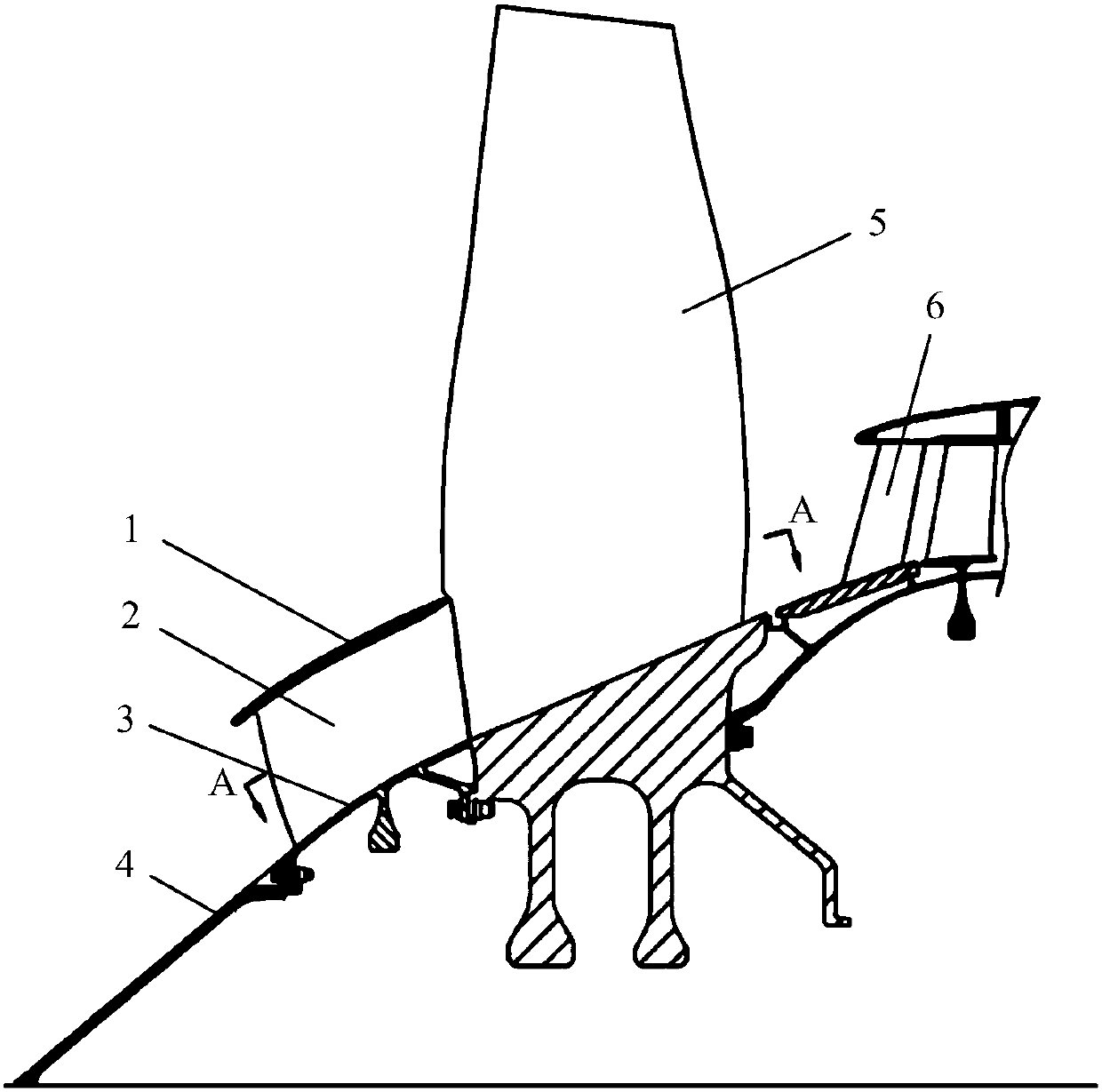
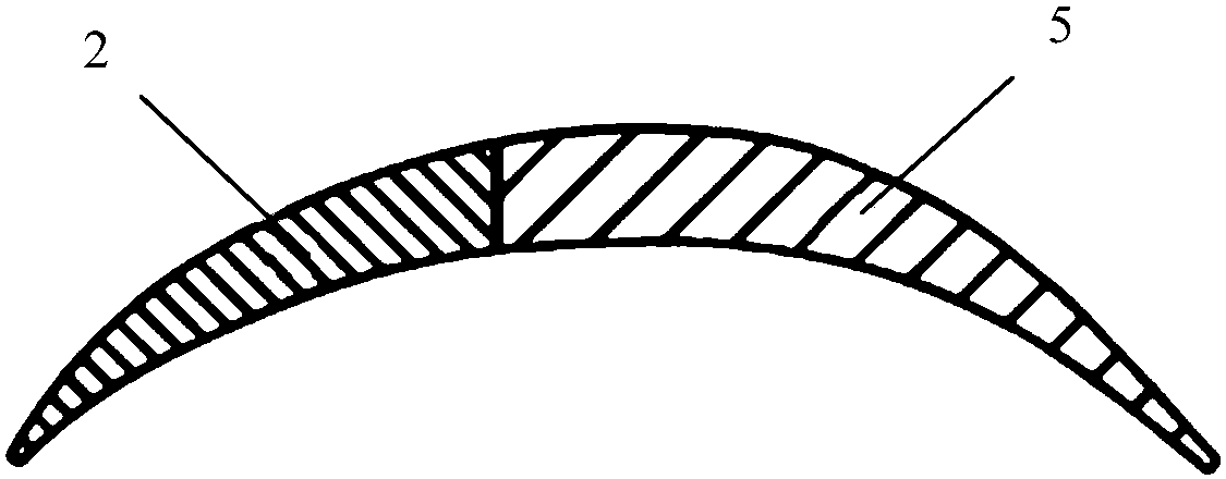
[0020] Figure 1 to Figure 2 As shown, according to the present invention, the new pre-compression configuration for the aeroengine compression system is...


PUM


Abstract

The invention provides a high bypass ratio turbofan engine and an aero engine compression system. The high bypass ratio turbofan engine and the aero engine compression system can improve the overall supercharging effect of a fan inner duct and an increasing level under the premise of increasing the engine mass as little as possible. The aero engine compression system includes a pre-compression configuration, and the pre-compression configuration is located at the front end of a fan rotor and at the rear end of an air inlet cone; the pre-compression configuration includes a rectifying outer ring, a plurality of blades and an internal flow passage ring, the rectifying outer ring is located at an outer ring, the internal flow passage ring is located at an inner ring, and the multiple blades are located between the outer ring and the inner ring; and the rectifying outer ring, the blades and the internal flow passage ring constitute a contraction passage.

Description

technical field [0001] The present invention relates to aeroengine compression systems. Background technique [0002] At present, in the domestic and foreign aero-engine compression systems, the supercharging stage with the same speed as the fan rotor is mainly used to do work on the gas in the internal channel behind the fan blades. [0003] In order to increase the compression effect, US6173566B1 discloses a pre-compression solution, which is realized by a detachable booster stage. DE 10 2014 226 696 A1 discloses that a precharger is arranged upstream of the fan, but this precharger is also a booster stage consisting of a plurality of blades. The pre-charger used in DE4131713A1 is also in the form of booster stage blades. [0004] The following problems exist in this type of design technique: [0005] Limited by the flow velocity at the tip of the fan blade, the rotor speed of the fan and the booster stage cannot be very high, which makes the boosting effect of the gas ...

Claims


Application Information

Patent Timeline
IPC IPC(8): F04D29/26F02K3/06
CPCF02K3/06F04D29/26F05D2220/36F05D2300/174F05D2300/6034
Inventor 李迪陈云永刘晓锋王家广秦文
Owner AECC COMML AIRCRAFT ENGINE CO LTD
Why Eureka
Try Eureka