Novel vertical vehicle turbocharger

A turbocharger, vertical vehicle technology, applied in gas turbine devices, machines/engines, internal combustion piston engines, etc., can solve the problems of reducing the charging efficiency of the engine cylinder, reducing the supercharging efficiency of the supercharger, and not solving the problems. The effect of improving the charging efficiency, ensuring the supercharging efficiency and reasonable structure

Inactive Publication Date: 2009-09-02
费传华
View PDF0 Cites 3 Cited by
  • Summary
  • Abstract
  • Description
  • Claims
  • Application Information

AI Technical Summary

Problems solved by technology

When this vehicle turbocharger works, wear and noise are small, and it can self-supply oil, and no oil supply system needs to be set, but it still has the following deficiencies in its work: 1. The inlet on the turbine housing is in the initial stage of air intake. There is one air passage, and after it is connected with the multi-cylinder engine, when multiple airflows of the multi-cylinder engine with different flow rates enter from one passage at the same time, they will interfere with each other, which will reduce the charging efficiency of the engine cylinder; 2. Due to the The inner cavity and the inner cavity of the compressor casing are connected. When working, when there is a pressure difference between the two inner cavities, the gas in the high-pressure inner cavity will flow to the lower-pressure inner cavity, which will reduce the boost pressure. booster efficiency
By retrieval, existing other vehicle turbochargers still have not solved the problems of these two aspects

Method used


Image

  • Novel vertical vehicle turbocharger
  • Novel vertical vehicle turbocharger
  • Novel vertical vehicle turbocharger

Examples


Embodiment Construction

[0010] The present invention is further described below in conjunction with embodiment and accompanying drawing.

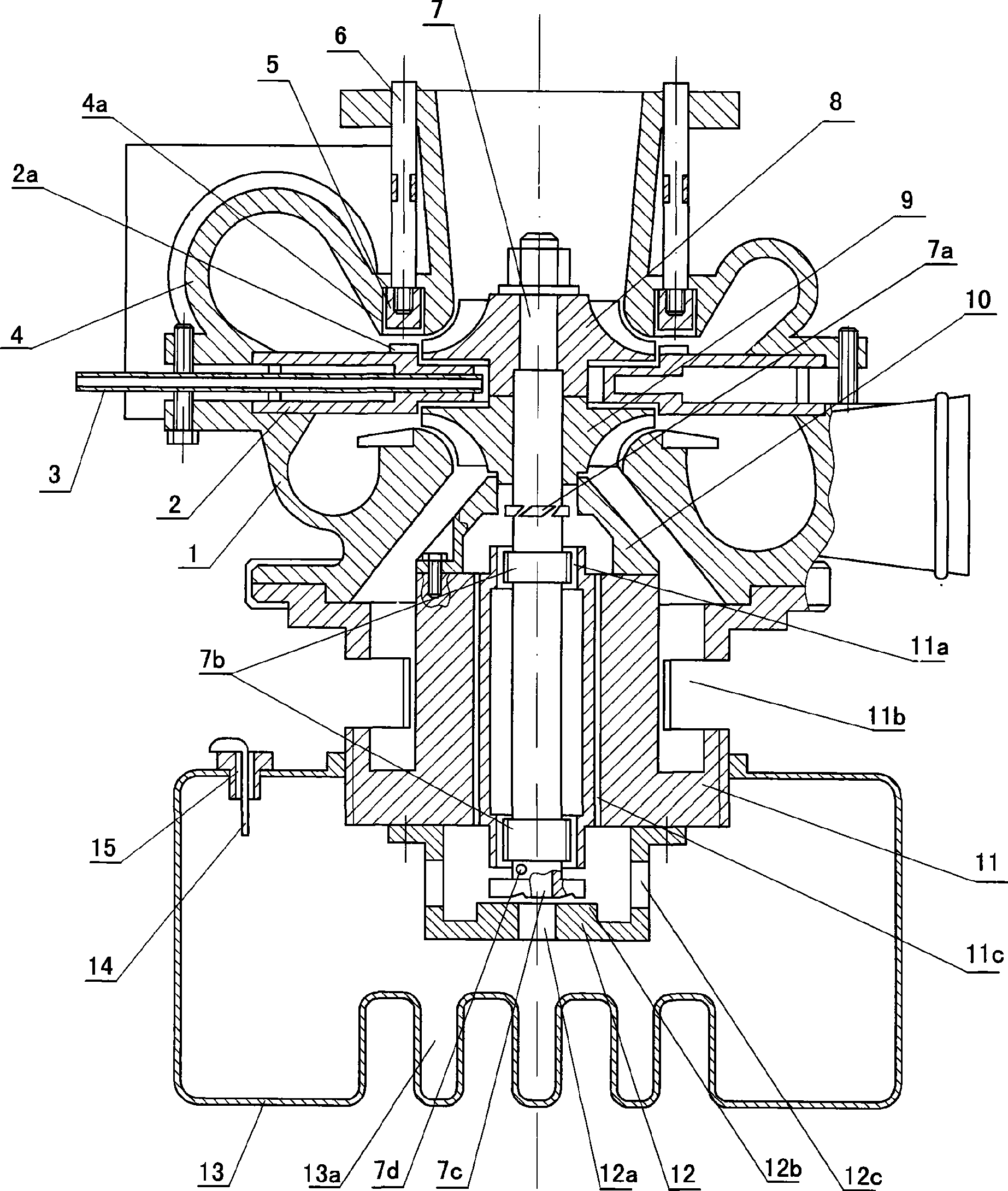
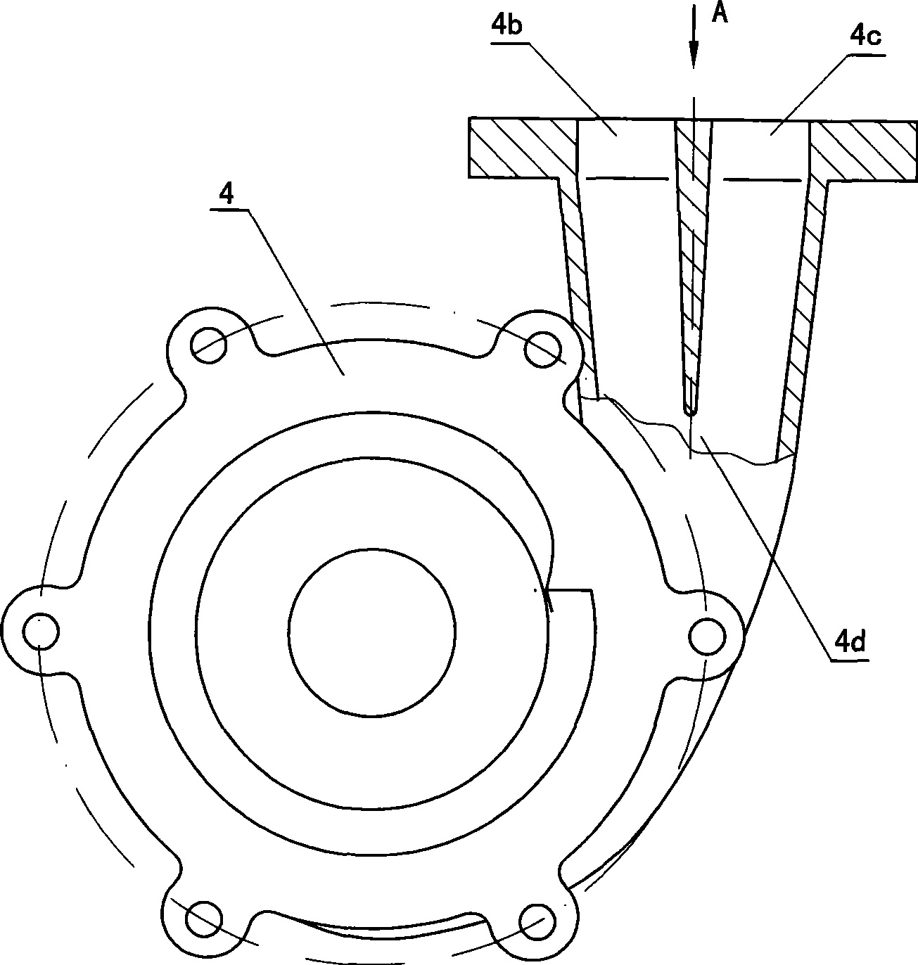
[0011] The connected turbine casing 4 and the compressor casing 1 are separated by a heat shield 2 between their inner cavities, the turbine casing 4 and the compressor casing 1 are connected by bolts, and the heat shield 2 is located in the turbine casing 4 On one side of the nozzle vanes 2a uniformly distributed along the throat of the turbine shell 4 are fixed. The compressor housing 1 is supported by a bearing housing 11 , and the bearing housing 11 is provided with an air inlet 11 b communicating with the inner cavity of the compressor housing 1 . The top of the rotating shaft 7 installed in the bearing housing 11 is located in the compressor casing 1 and the turbine casing 4, and the turbine 8 and the compressor impeller 9 installed on the top of the rotating shaft 7 are respectively in the turbine casing 4 and the compressor casing 1. Turbine 8 is a radial...


PUM


Abstract

The invention discloses a novel vertical vehicle turbocharger. A thermal baffle is arranged between a turbine shroud and a compressor casing, wherein the turbine shroud and the compressor casing are connected together. The compressor casing is supported by a bearing shell having an air inlet. The upper part of a rotating shaft arranged inside the bearing shell is positioned in the compressor casing and the turbine shroud. A turbine and a compressor impeller which are arranged on the upper part of the rotating shaft are positioned in the turbine shroud and the compressor casing respectively. The lower end of the bearing shell is connected with an oil tank, and the lower end of the rotating shaft is positioned in the oil tank. Two induction trunks are arranged on the turbine shroud for the initial charging stage and arranged at a place where the entrances of the air channels meet in the turbine shroud and are in smooth connection with the entrances of the air channels. A conduit runs through the thermal baffle to reach a place between the turbine and compressor impellor. The turbocharger is simple in structure, reliable in use, good in self-pressurization and capable of improving the charging efficiency of a cylinder of an engine.

Description

technical field [0001] The invention relates to a vehicle turbocharger which utilizes the exhaust gas discharged from a diesel engine or a gasoline engine for supercharging. Background technique [0002] An existing vertical vehicle turbocharger, its main structure is: a heat insulation plate is separated between the connected turbine casing and the compressor casing, the compressor casing is supported by a bearing casing, and an air inlet is provided on the bearing casing The upper part of the rotating shaft installed in the bearing housing is located in the compressor housing and the turbine housing, the turbine and the compressor impeller installed in the upper part of the rotating shaft are respectively located in the turbine housing and the compressor housing, and the lower end of the bearing housing is connected to an oil tank. The lower end is located in the oil tank, and the rotating shaft is located in the shaft section of the bearing shell. There are two sections o...

Claims


Application Information

Patent Timeline
Patent Type & Authority Applications(China)
IPC IPC(8): F02B37/00F02C6/12
CPCY02T10/144Y02T10/12
Inventor 费传华
Owner 费传华
Why Eureka
Try Eureka