Fuel gas mold temperature controller

A technology of mold temperature control and gas, which is applied in the direction of combustion method, combustion control, and fuel supply adjustment, etc. It can solve the problems of poor heat dissipation, insufficient heat exchange, and unfavorable flue gas heat exchange, etc., and achieves convenient control and automatic procedures. high effect

Inactive Publication Date: 2017-02-08
DONGTAI SANCANG ENERGY SAVING BOILER
View PDF5 Cites 4 Cited by
  • Summary
  • Abstract
  • Description
  • Claims
  • Application Information

AI Technical Summary

Problems solved by technology

For the above-mentioned essentials, corresponding devices or systems are installed on the existing machines, but the actual use effect is not ideal due to technical or other reasons. The heat dissipation pipe used is an ordinary steel pipe with a smooth inner wall, so there is basically no flow resistance when the flue gas flows in the pipe, and the flow velocity of the flue gas in the pipe is relatively fast. There is still a large amount of heat in the gas that is discharged to the atmosphere together with the flue gas, and the absorption effect of heat reuse is not good. After the flue gas flows in the pipe for a long time, the smoke will inevitably form a cylindrical fouling layer on the inner wall of the pipe. When the tube is heated or cooled, the cylindrical fouling layer will form a uniform stress inside. The cylindrical fouling layer has relatively strong adhesion on the tube wall and is not easy to peel off by itself, so the heat dissipation performance of the heat pipe will be affected. , especially as the fouling layer becomes thicker, the heat dissipation will become worse and worse, which directly leads to the high temperature of the exhausted flue gas, which cannot meet the emission requirements, and the current high-temperature flue gas heat recovery The high-temperature flue gas introduction box and the low-temperature flue gas discharge box in the device are respectively arranged at both ends of the heating medium box, then the flue gas is directly discharged from the low-temperature flue gas discharge box after being introduced into the heat dissipation pipe by the high-temperature flue gas introduction box, and the flue gas heat dissipation stroke It is equivalent to the length of the heat dissipation pipe, and the heat dissipation time is short, which is not conducive to the full exchange of flue gas heat. In addition, in the heating medium box, the medium introduced into the box by the medium inlet pipe is directly discharged by the medium discharge pipe, so that in the heating medium box The heat exchange time between the heating medium inside and the heat dissipation pipe is relatively short, and it is difficult for the heating medium to rise to the expected temperature value, which will affect the normal operation of subsequent heat application equipment; On the oil-gas separator, the axial angles between the axis of the oil inlet pipe, the axis of the oil outlet pipe and the central axis of the tank are all set as vertical angles. The swirl flow is formed on the liquid layer corresponding to the nozzle of the oil pipe and perpendicular to the central axis of the tank, and the same is true at the oil outlet pipe, so that there is a lack of fluid flow in the liquid layer between the oil inlet pipe and the oil outlet pipe. The flushing force of swirling and cleaning is not conducive to the formation of bubbles of the gas dissolved in the hot oil, which also inhibits the overflow of the gas. The formation of the overflow is not complete, and the oil pressure of the oil outlet will still fluctuate to a certain extent. Accordingly, the heating equipment The temperature will also fluctuate, making it difficult for the heating equipment to reach a stable working state; third, the oil temperature control system used on the current machine is composed of relays and contactors. Slow speed and low control precision make it difficult to control the oil temperature within the desired range

Method used


Image

  • Fuel gas mold temperature controller
  • Fuel gas mold temperature controller
  • Fuel gas mold temperature controller

Examples


Embodiment Construction

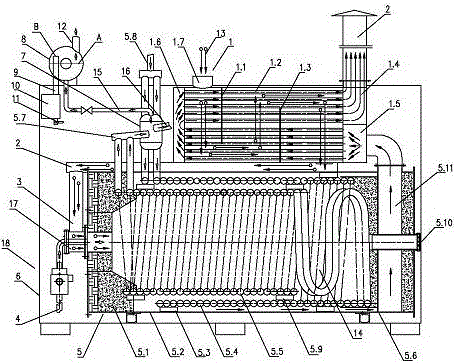
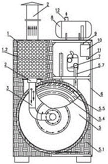
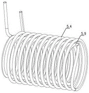
[0025] exist figure 1 and figure 2 In the gas-fired mold temperature controller shown, a heat-conducting oil furnace 5 is fixedly installed on the frame 6, and a coil is arranged in the combustion chamber 14 of the heat-conducting oil furnace 5, and the coil is separated from the inner wall of the furnace by a spacer - 5.3 , the pitch P of the coil is 2.2 times the diameter d of the pipe, and the coil is formed by connecting the outer coil 5.4 and the inner coil 5.5 coaxially (see image 3 ), the outer coil 5.4 and the inner coil 5.5 are separated by a spacer 5.3, there are two coils, and the two coils are interlaced with each other and connected in parallel (see Figure 4 ), the two oil inlet pipes 5.8 of the two coils are connected in parallel to a general oil inlet pipe, and the oil inlet oil temperature sensor 18.10 and the oil inlet oil pressure gauge 18.11 are installed on the general oil inlet pipe. The two oil outlet pipes 5.7 are connected in parallel to a general ...


PUM


Abstract

The invention discloses a fuel gas mold temperature controller. The fuel gas mold temperature controller comprises a rack and a heat conduction oil furnace. A smoke heat recoverer is arranged on the rack which is above the heat conduction oil furnace. One end of the smoke heat recoverer is connected with a smoke chamber and a smoke guiding-in chamber in a sealed mode, and a smoke reversing chamber is arranged at the other end of the smoke heat recoverer in a sealed mode. A plurality of thread smoke tubes are arranged in the smoke heat recoverer in parallel. An oil-gas separation tank and an oil overflowing tank are arranged on the rack which is above the heat conduction oil furnace. The oil-gas separation tank is located below the oil overflowing tank. The oil-gas separation tank is communicated with a coiled tube through an oil outlet tube, the oil outlet tube is arranged on one side of the oil-gas separation tank, a separation tank oil outlet tube is arranged on the other side of the oil-gas separation tank, and the oil-gas separation tank is communicated with the oil overflowing tank. The rack is further provided with an oil temperature control device. The fuel gas mold temperature controller has the benefits that the smoke heat conversion efficiency is good, oil-gas separation is sufficient and thorough, and the oil temperature control is stable and high in precision.

Description

technical field [0001] The invention relates to a gas mold temperature controller, in particular to an improvement on the structure of the gas mold temperature controller. Background technique [0002] As a device that provides energy to heat-consuming equipment through thermal energy conversion, the mold temperature controller has been widely used in industrial production. In the mold temperature machine, in order to reduce the temperature of the high-temperature flue gas discharged from its combustion chamber to meet the emission standard, the high-temperature flue gas is usually introduced into a heat recovery device that can absorb and reuse the heat of the flue gas; Dissolved gas in the oil is discharged from the oil to prevent the dissolved gas from forming unbalanced pressure on the oil in the pipeline, resulting in pressure fluctuations, resulting in unstable oil outlet pressure, unbalanced hot oil flow rate, and resulting temperature fluctuations in the heating equi...

Claims


Application Information

Patent Timeline
Patent Type & Authority Applications(China)
IPC IPC(8): F24H7/00F24H9/20F23N1/02
CPCF23N1/02F24H7/005F24H9/2035F23N2239/04
Inventor 孔世林孔凡成
Owner DONGTAI SANCANG ENERGY SAVING BOILER
Why Eureka
Try Eureka