Compound sliding block structure

A composite type and slider technology, applied in the field of die-casting molds, can solve problems such as inability to effectively eliminate air trapping in products, low yield rate, complex structure, etc., and achieve the effect of simple structure, low cost, and easy manufacturing

Active Publication Date: 2012-01-18
NINGBO JUNLING MOLD TECH
View PDF9 Cites 4 Cited by
  • Summary
  • Abstract
  • Description
  • Claims
  • Application Information

AI Technical Summary

Problems solved by technology

[0003] The purpose of the present invention is to overcome the technical problems that the existing slider mechanism cannot effectively eliminate the trapped air inside the product, the yield rate is low, and the structure is complex, and to provide a simple, safe and reliable composite slider structure, which can effectively eliminate The trapped air in the middle of the product can achieve the effect of fully exhausting the product, thereby improving the composite slider structure of the yield

Method used


Image

  • Compound sliding block structure
  • Compound sliding block structure
  • Compound sliding block structure

Examples


Embodiment

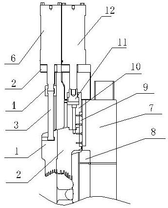
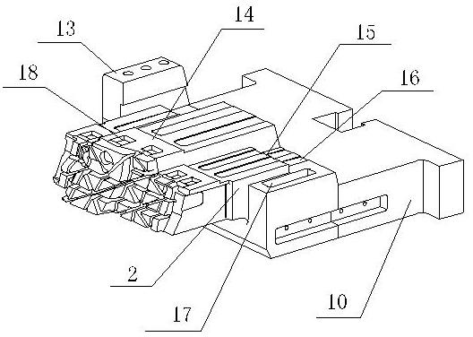
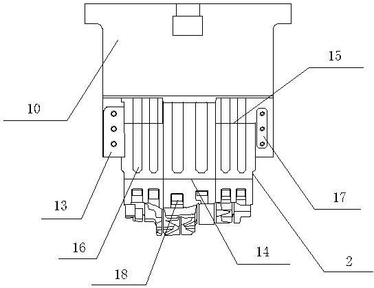
[0021] Example: such as figure 1 As shown, a composite slider structure includes an oil cylinder, a composite slider, a movable mold frame 7 and a movable mold core 8, the movable mold frame 7 and the movable mold core 8 form a movable mold, and the composite slider includes a driven slider 1 and a movable mold core 8. The lower basic slider 2 has six parallel process slag discharge grooves 16 on the upper end surface of the lower basic slider 2, which are used to remove the aluminum skin blown or squeezed in during the movement of the composite slider, and oil cooling Liquid, etc., to ensure smooth and safe mechanical movement, one end of the process slag discharge tank 16 points to the front end of the lower basic slider 2, and the other end points to the rear end of the lower basic slider 2, and at the same time, it is integrated on the upper end surface of the lower basic slider 2 A first progress hindering part 14 and a second progress hindering part 15 are made, and the ...


PUM


Abstract

The invention relates to a die casting mold, in particular to a compound sliding block structure in the die casting mold. In order to overcome the technical problem of low finished product rate because the traditional sliding block mechanism can not effectively eliminate trapped gas in the finished product, the invention provides the compound sliding block structure which has simple structure andis safe and reliable; meanwhile, the compound sliding block structure is characterized in that the trapped gas in the middle of the sliding block can be effectively eliminated so as to achieve the effect on fully venting the product to improve the finished product rate. The compound sliding block structure comprises a compound sliding block, oil cylinders, a movable mold frame and a movable mold core, wherein a movable mold is in slip connection with the bottom surface of the compound sliding block; the compound sliding block comprises a driven sliding block and a bottom basic sliding block; the upper oil cylinder is connected with the driven sliding block; the lower oil cylinder is connected with the bottom basic sliding block; the front end of the bottom basic sliding block is provided with a deslagging air vent; and the upper end surface of the bottom basic sliding block is provided with a technical deslagging slot.

Description

technical field [0001] The invention relates to a die-casting mold, and more specifically relates to a composite slider structure in the die-casting die. Background technique [0002] At present, high-pressure casting technology is used in many fields, such as the core part of heavy machinery, that is, the shell. Due to the heavy weight of its products, the molds used are also large-scale molds, and the structure of the product is complex, with multiple ribs. The geometric dimensions are large, so the die-casting mold used also becomes complex in structure, the runner filling distance is long, and the distal end is difficult to form, which leads to excess trapped air during the die-casting process. Once these trapped air It cannot be ruled out that the manufactured products will become waste products. Although an exhaust groove has been added under the far end, due to the high requirements of the product, the trapped air formed in the middle cannot be discharged at all. This...

Claims


Application Information

Patent Timeline
Patent Type & Authority Applications(China)
IPC IPC(8): B22D17/22
Inventor 姚贤君崔龙胡宁安张远岳
Owner NINGBO JUNLING MOLD TECH
Why Eureka
Try Eureka