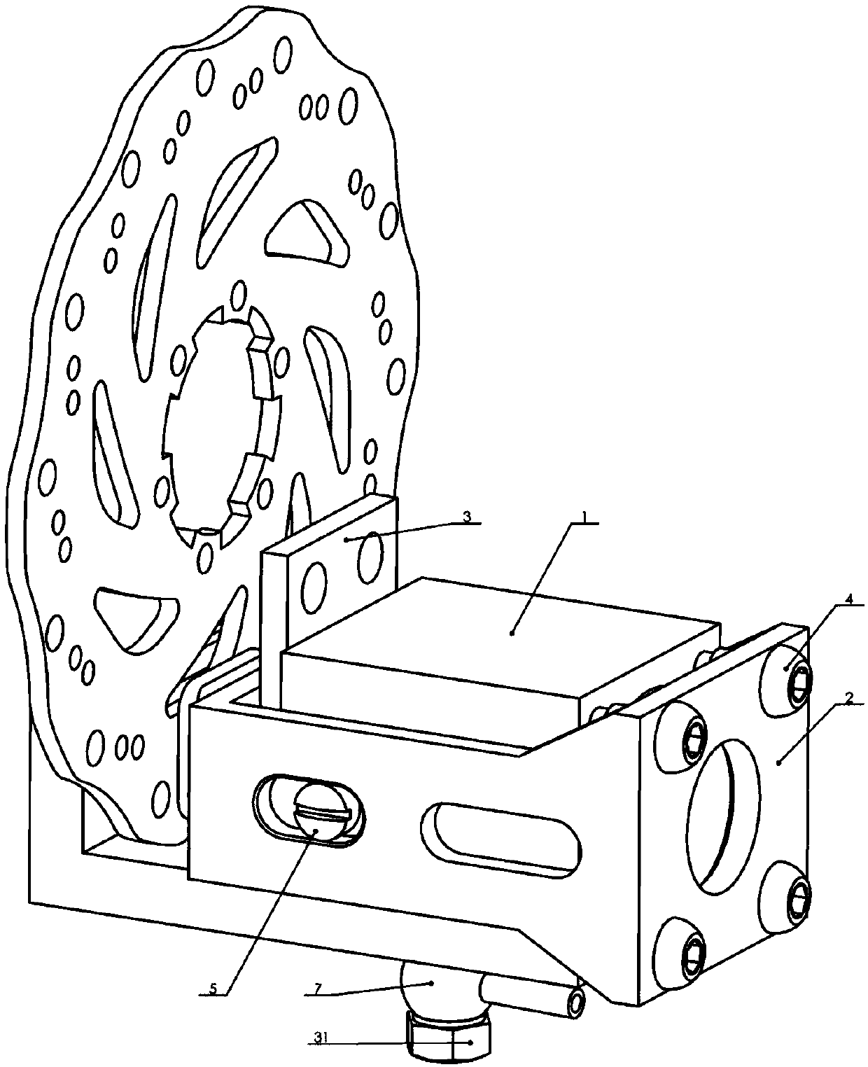
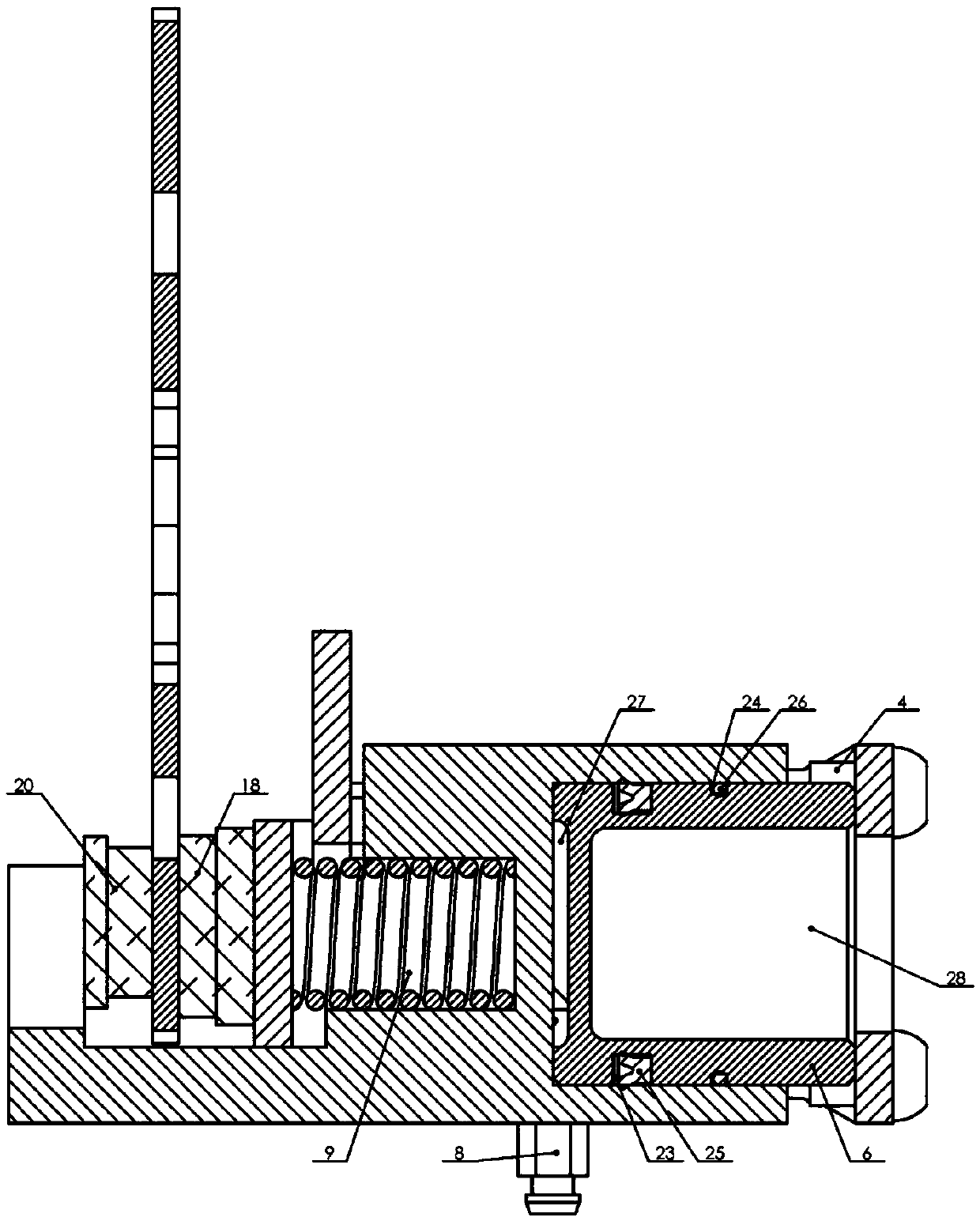
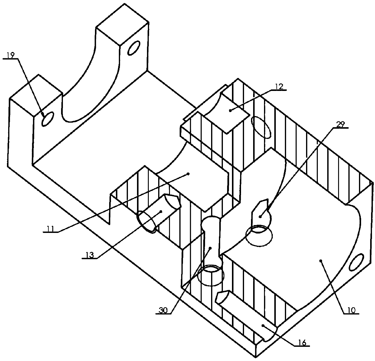
External connection type normal-locking hydraulic disc brake device

A hydraulic and disc brake technology, which is applied in the field of externally connected constant-lock hydraulic disc brake devices, can solve problems such as unfavorable processing, complex structure, and easy damage, and achieve the goal of reducing manufacturing difficulty, avoiding self-locking phenomenon, and avoiding instability Effect

Active Publication Date: 2019-03-29
YANSHAN UNIV
View PDF6 Cites 3 Cited by
  • Summary
  • Abstract
  • Description
  • Claims
  • Application Information

AI Technical Summary

Problems solved by technology

Some active brakes have great potential safety hazards due to human operation, such as universal wheels with brakes and brakes used on baby carriages.
At present, all kinds of brakes on the market are normally open brakes, especially in the field of hydraulic disc brakes, which are active brakes. The structure of the normally open hydraulic disc brake device is complicated, and the design of the sealing groove is unreasonable, which is not conducive to processing. The pressure oil achieves the braking effect by pushing the piston to squeeze the friction plate. However, there is a great demand for normally closed brakes in daily work and life.
Some permanent lock brakes use rigid brakes, which have a large impact on the mechanical structure, especially when braking during exercise, and are very easy to damage, such as the use of stuck gears or truck wheels, affecting user experience

Method used


Image

  • External connection type normal-locking hydraulic disc brake device
  • External connection type normal-locking hydraulic disc brake device
  • External connection type normal-locking hydraulic disc brake device

Examples


Embodiment Construction

[0019] In order to make the purpose, technical solutions and advantages of the embodiments of the present invention clearer, the technical solutions in the embodiments of the present invention will be clearly and completely described below in conjunction with the drawings in the embodiments of the present invention. Obviously, the described embodiments It is a part of embodiments of the present invention, but not all embodiments.

[0020] In describing the present invention, it is to be understood that the terms "radial", "axial", "upper", "lower", "top", "bottom", "inner", "outer" etc. indicate orientation Or the positional relationship is based on the orientation or positional relationship shown in the drawings, which is only for the convenience of describing the present invention and simplifying the description, and does not indicate or imply that the referred device or element must have a specific orientation, be constructed and operated in a specific orientation , and the...


PUM


Abstract

The invention discloses an external connection type normal-locking hydraulic disc brake device. The device comprises a main clamp body, an external connecting frame, a mounting plate, jackscrews, guide screws, a piston and a spring; and the device is characterized in that a piston hole is formed in the bottom of the main clamp body, the piston is pressed in the piston hole in a matched mode, a spring guide hole is formed in the middle of the main clamp body, the spring is compressed in the spring guide hole, guide threaded holes are formed in the middles of the left side face and the right side face of the main clamp body respectively, guide groove holes are formed in the left side face and the right side face of the external connecting frame respectively, the front ends of the guide screws are installed in the guide threaded holes through threads, the rear ends of the guide screws are clamped in the guide groove holes, four threaded mounting holes are uniformly distributed in the rearend face of the external connecting frame, four guide unthreaded holes are uniformly distributed in the end face of the bottom of the main clamp body, the rear ends of the jackscrews are connected into the threaded mounting holes through threads, the front ends of the jackscrews are installed in the guide unthreaded holes, a supporting guide column is fixedly connected to the mounting plate through riveting, the supporting guide column is installed in a guide hole, and a pit is formed in the end face of the outer side of the piston.

Description

technical field [0001] The invention relates to the technical field of hydraulic brakes, in particular to an externally connected constant-lock hydraulic disc brake device. Background technique [0002] With the improvement of people's safety awareness, the braking method that relies on artificial active braking in the unlocked state under normal conditions can no longer meet people's needs. The constant lock brake that can only be moved through active unlocking under the normal state of braking is becoming more and more important, especially in This is especially important on rocking ships, large medical equipment, baby carriages, and mine delivery vehicles. Some active brakes have great potential safety hazards due to human operation, such as universal wheels with brakes and brakes used on baby carriages. At present, all kinds of brakes on the market are normally open brakes, especially in the field of hydraulic disc brakes, which are active brakes. The structure of the n...

Claims


Application Information

Patent Timeline
Patent Type & Authority Applications(China)
IPC IPC(8): F16D55/225
Inventor 边辉刘灿王东华赵铁石
Owner YANSHAN UNIV
Why Eureka
Try Eureka