
Digital measuring device and measuring method for cavity of fan-shaped segment welding blade

A measuring device and segment technology, which is applied in the field of fixtures and fixtures, can solve problems such as inability to give accurate data, achieve the effects of increasing the measuring range, simple measuring methods, and improving positioning accuracy

Active Publication Date: 2019-03-29
SHENYANG LIMING AERO-ENGINE GROUP CORPORATION
View PDF16 Cites 1 Cited by
  • Summary
  • Abstract
  • Description
  • Claims
  • Application Information

AI Technical Summary

Problems solved by technology

[0003] At present, there are generally 5 stages of welding blades in the fan-shaped section, and 8 blades are usually welded in the middle of each welding blade. In order to detect the welding quality, there are measurement points on the T-shaped plate and the flow channel plate respectively. On the traditional measuring tool , the blade is usually positioned horizontally, and reference blocks are designed on both sides of the T-shaped plate and the flow channel plate of the blade respectively. There are height reference planes and angle reference planes on the reference block for template measurement. Whether the blade welding points are qualified or not, accurate data cannot be given

Method used


Image

  • Digital measuring device and measuring method for cavity of fan-shaped segment welding blade
  • Digital measuring device and measuring method for cavity of fan-shaped segment welding blade
  • Digital measuring device and measuring method for cavity of fan-shaped segment welding blade

Examples


Embodiment Construction

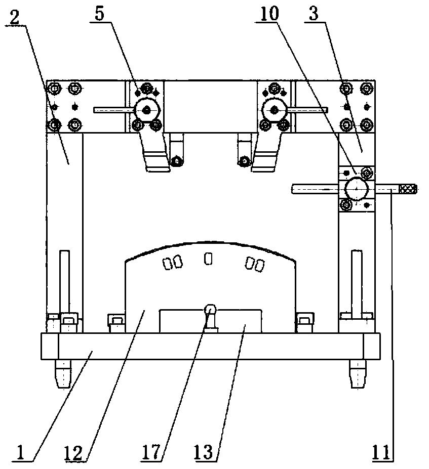
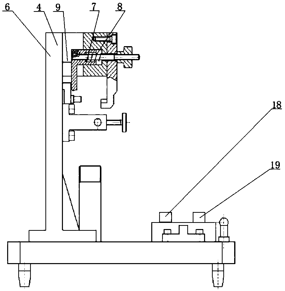
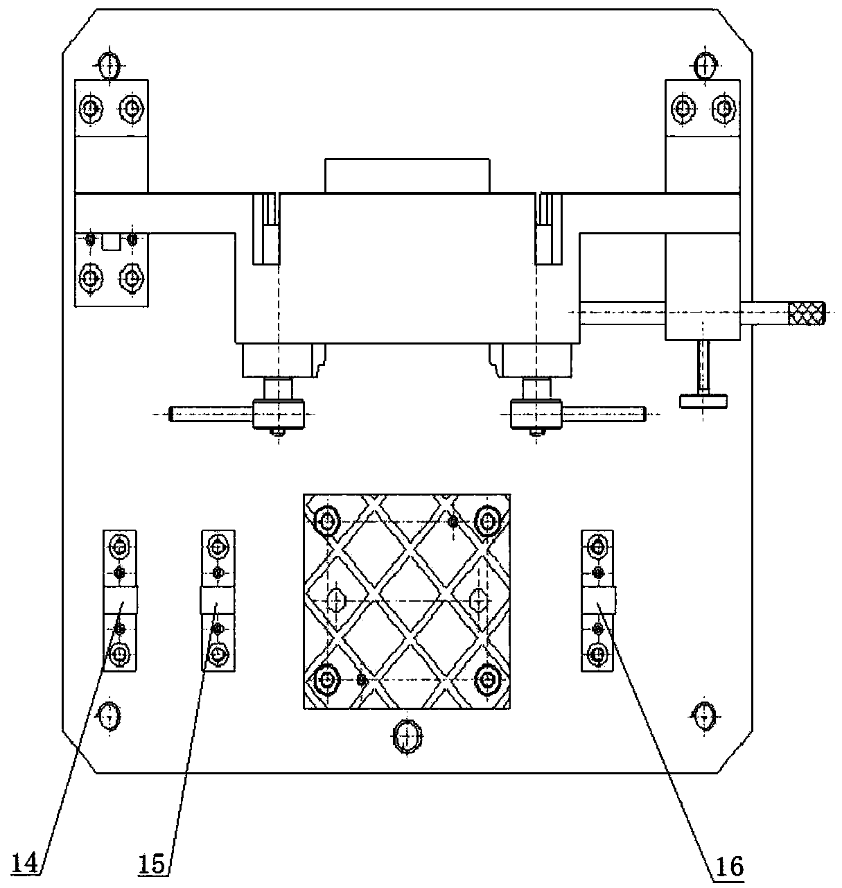
[0028] The present invention will be further described in detail below in conjunction with the accompanying drawings and embodiments.

[0029] Such as Figure 1-Figure 3 As shown, a digital measurement device for the cavity of a sector-shaped welded blade includes a positioning mechanism and a measuring mechanism. The upper surface of the bottom plate 1 of the positioning mechanism is provided with a measuring mechanism.

[0030] The positioning mechanism includes a base plate 1, the rear end of the upper surface of the base plate 1 is provided with a support one 2 and a support two 3, the top front end of the support one 2 and the support two 3 is provided with a support seat 4, and the front end of the support seat 4 A positioning block 5 is symmetrically arranged on the surface, a blind hole is provided on the rear end surface of the support seat 4, and a pressing block 6 is arranged in the blind hole, and a countersunk hole coaxial with the blind hole is opened on the pres...


PUM


Abstract

The invention provides a digital measuring device and a measuring method for a cavity of a fan-shaped segment welding blade. The digital measuring device comprises a positioning mechanism and a measuring mechanism. The measuring mechanism is arranged on the upper surface of the bottom plate of the positioning mechanism. The digital measuring method for the cavity of the fan-shaped segment weldingblade is characterized by vertical measuring the blade, improving the original measurement method of only measuring point by using a template to measure a rotating circular arc line, which increases the measuring range. When the digital measuring device for the cavity of the fan-shaped segment welding blade clamps and positions the blade, one side is positioned by using a positioning block, the other side is positioned by using a stop pin, the radial displacement is controlled through the stop pin, a pressing block connected with the positioning block is used for compressing, so that the positioning precision of the blade during the measurement process is improved, and the measurement error is reduced. The measuring mechanism of the digital measuring device for the cavity of the fan-shapedsegment welding blade slides on the circular reference by using a gauge stand having a digital readout instrument to measure. The measurement method is simpler, and the measurement results are more accurate and more intuitive.

Description

technical field [0001] The invention belongs to the technical field of tooling fixtures, and in particular relates to a digital measuring device and a measuring method for the cavity of a sector-shaped welded blade. Background technique [0002] The fan section welding blade is an important part of the compressor. It is composed of a T-shaped plate, a flow channel plate, a large and small bent blade plate and blades. Since the welding blade is welded by multiple parts, according to the process requirements: The distance between the T-shaped plate of the blade cavity and the corresponding point of the flow channel plate should be kept constant. In order to ensure the accuracy of the measurement of the welded blade cavity, a measuring tool is needed to realize the dimensional measurement control during the processing. [0003] At present, there are generally 5 stages of welding blades in the fan-shaped section, and 8 blades are usually welded in the middle of each welding blad...

Claims


Application Information

Patent Timeline
Patent Type & Authority Applications(China)
IPC IPC(8): G01B5/00
CPCG01B5/00G01B5/0002
Inventor 陈佳慧赵海涛宋子明李有孙丽丽
Owner SHENYANG LIMING AERO-ENGINE GROUP CORPORATION
Learn More