Multi-channel current collecting system with wide temperature range and high precision

An acquisition system and high-precision technology, applied in the direction of measurement using digital measurement technology, can solve the problems of rough and inaccurate acquisition methods, and achieve the effects of light weight, high current accuracy, and small size

Active Publication Date: 2019-03-29
重庆嘉陵华光光电科技有限公司
View PDF19 Cites 3 Cited by
  • Summary
  • Abstract
  • Description
  • Claims
  • Application Information

AI Technical Summary

Problems solved by technology

[0002] At present, the instruments and equipment in the reconnaissance vehicle used to monitor the electrical current of each reconnaissance equipment mostly use current transformers to collect the induced current on the wires and obtain the current value after processing and calculation. This collection method is relatively rough and not ideal. Accurate, not applicable in some occasions that require high accuracy of current value

Method used


Image

  • Multi-channel current collecting system with wide temperature range and high precision
  • Multi-channel current collecting system with wide temperature range and high precision
  • Multi-channel current collecting system with wide temperature range and high precision

Examples


Embodiment 1

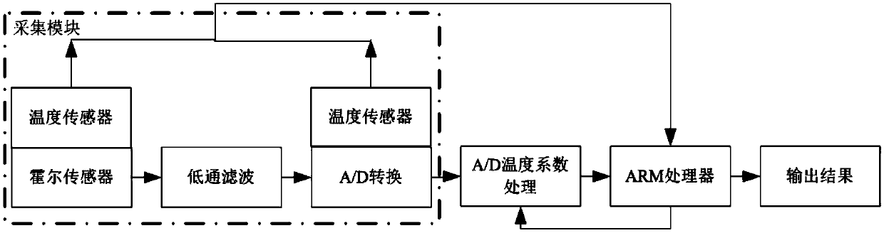
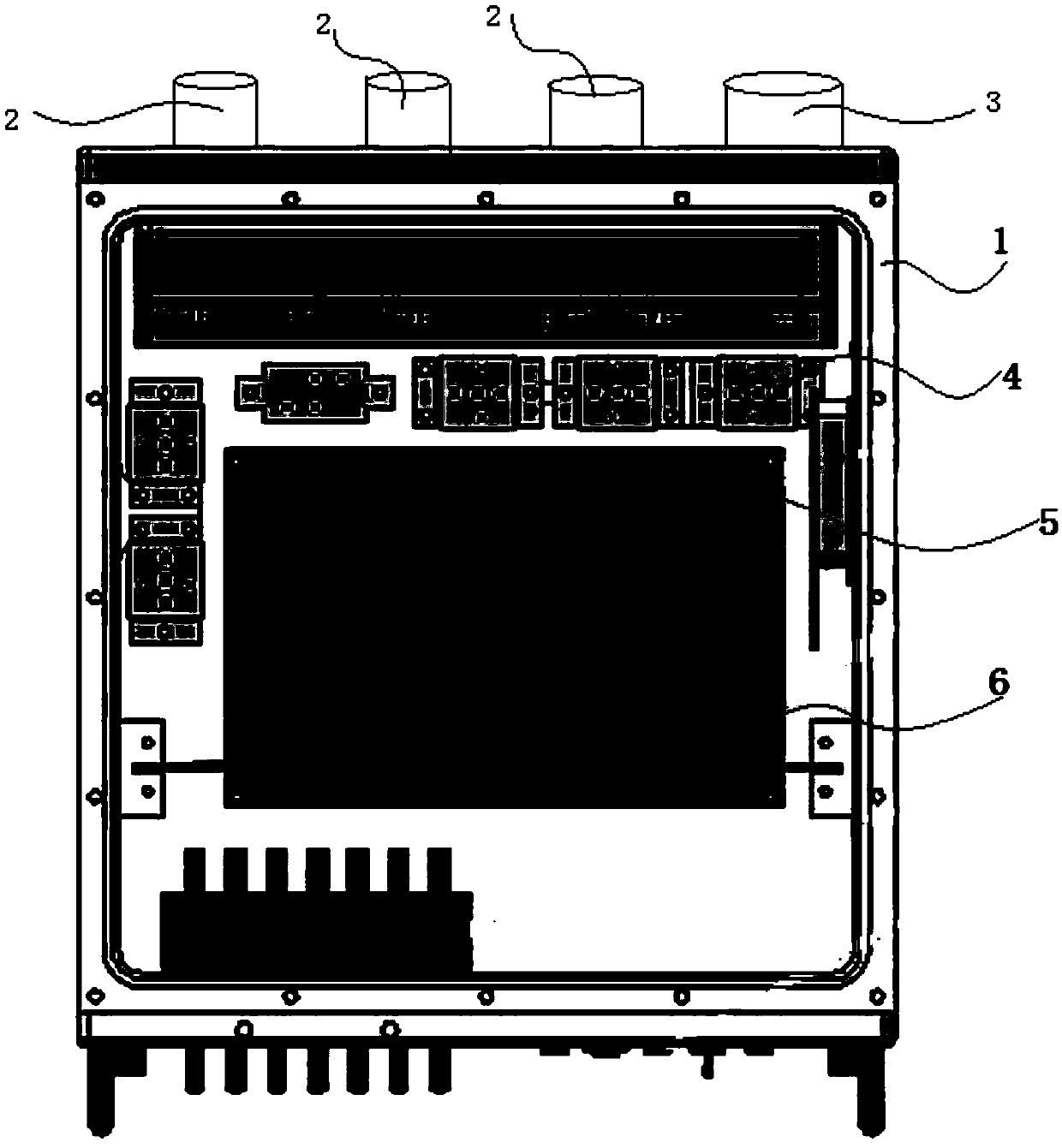
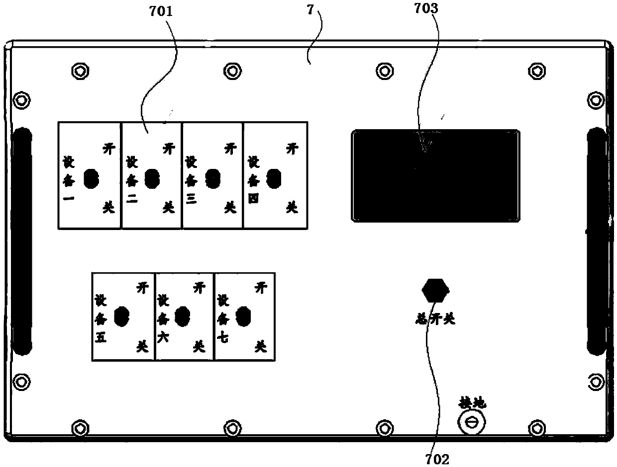
[0059] see Figure 1 to Figure 3 , Wide-temperature high-precision multi-channel current acquisition system, mainly includes a housing 1, a power input socket 2, an output socket 3, a relay 4, n sensing modules 5, a control circuit board 6 and a front panel 7. n=7.

[0060] The housing 1 is a box, and the six outer surfaces are respectively marked as a first side wall, a second side wall, a third side wall, a fourth side wall, a fifth side wall and a sixth side wall. And the first side wall is opposite to the third side wall, the second side wall is opposite to the fourth side wall, and the fifth side wall is opposite to the sixth side wall.

[0061] The power input socket 2 and the output socket 3 are arranged on the first side wall of the casing 1 .

[0062] The power input socket 2 is connected to the power supply, and the current of the power supply flows through the relay 4 and n sensing modules 5 and then is output to the external device through the output socket 3 . ...

Embodiment 2

[0124] see Figure 4 , the circuit structure of the wide-temperature high-precision multi-channel current acquisition system is as follows:

[0125] The input current is input into 7 external devices through 7 input switches, and the input current is respectively recorded as I1, I2, I3, I4, I5, I6 and I7.

[0126] The 7 sensing modules respectively measure the voltage values ​​and corresponding temperature values ​​of 7 external devices.

[0127] The voltage values ​​are respectively recorded as Vin1, Vin2, Vin3, Vin4, Vin5, Vin6 and Vin7.

[0128] The temperature values ​​are recorded as t1, t2, t3, t4, t5, t6 and t7, respectively.

[0129] The voltage Vin1 flows through the resistor R1. Voltage Vin2 flows through resistor R2. Voltage Vin3 flows through resistor R3. Voltage Vin4 flows through resistor R4. Voltage Vin5 flows through resistor R5. Voltage Vin6 flows through resistor R6. Voltage Vin7 flows through resistor R7.

[0130] The resistor R1 and the capacitor C...


PUM


Abstract

The invention discloses a multi-channel current collecting system with a wide temperature range and high precision, which mainly comprises a casing, a power input socket, an output socket, a relay, nsensing modules, a control circuit board, and a front panel. The power input socket is connected with a power supply. The current of the power supply flows through the relay, n sensing modules, and then is output to an external device through the output socket. The output socket is connected to n external devices. The Hall sensor respectively measures the induced voltage values of the current operating currents of the n external devices and sends them to the control circuit board. The temperature sensor measures the temperature value of the Hall sensor and sends it to the control circuit board. The control circuit board calculates the current value of the external device based on the received temperature value and voltage value. The system uses a temperature sensor, an integrated Hall current collector, and a high-precision A / D converter to achieve a processing system that has a current accuracy of 0.1A and simultaneously detects multiple devices in a wide temperature range of -40 DEGC to +55 DEG C.

Description

technical field [0001] The invention relates to the field of equipment electricity monitoring, in particular to a wide-temperature and high-precision multi-channel current acquisition system. Background technique [0002] At present, the instruments and equipment in the reconnaissance vehicle used to monitor the electrical current of each reconnaissance equipment mostly use current transformers to collect the induced current on the wires and obtain the current value after processing and calculation. This collection method is relatively rough and not ideal. Accurate, it is not applicable in some occasions that require high accuracy of current value. Contents of the invention [0003] The purpose of the present invention is to solve the problems existing in the prior art. [0004] The technical solution adopted in order to realize the object of the present invention is such that the wide-temperature high-precision multi-channel current acquisition system mainly includes a h...

Claims


Application Information

Patent Timeline
Patent Type & Authority Applications(China)
IPC IPC(8): G01R19/25
CPCG01R19/25
Inventor 周丽娜骆鑫陈武雄陈建平郑红川杨锦程
Owner 重庆嘉陵华光光电科技有限公司
Why Eureka
Try Eureka