A method and device for calibrating amplitude and phase of array radiometer channel

A calibration method and radiometer technology, applied in measurement devices, instruments, measuring electrical variables, etc., can solve the problems of inability to control a single channel switch, increase test complexity, affect measurement accuracy, etc., and achieve low cost, simple composition, and calibration. Simple process effect

Active Publication Date: 2020-04-24
BEIHANG UNIV
View PDF2 Cites 0 Cited by
  • Summary
  • Abstract
  • Description
  • Claims
  • Application Information

AI Technical Summary

Problems solved by technology

The disadvantage of this method is that it will introduce the measurement of the phase, which increases the complexity of the test
This method is fast, but it is mostly used in digital phase shifters. The quantization error introduced by digital phase shifters will affect the measurement accuracy of this method, and the calculation process is relatively complicated. When solving the phase at the end, it is necessary to consider the multi-valued problem of the solution.
[0008] Considering that in the actual array radiometer system, the received signal of each channel will be directly power detected after passing through the combiner, so it is impossible to control the switch of a single channel, and the phase shifter used in the radiometer system is an analog phase shifter, and at the same time In order to reduce the test equipment, a suitable fast, simple and easy-to-implement array radiometer channel amplitude and phase calibration method and device are needed

Method used


Image

  • A method and device for calibrating amplitude and phase of array radiometer channel
  • A method and device for calibrating amplitude and phase of array radiometer channel
  • A method and device for calibrating amplitude and phase of array radiometer channel

Examples


Embodiment Construction

[0034] The present invention will be described in detail below in conjunction with the accompanying drawings and embodiments.

[0035] Taking the one-dimensional 16-element array as an example, the system channel phase residual error index requirement after calibration of the array radiometer is

[0036] where Δθ i is the calibrated phase residual of the i-th channel, Average of phase residuals after calibration for N channels.

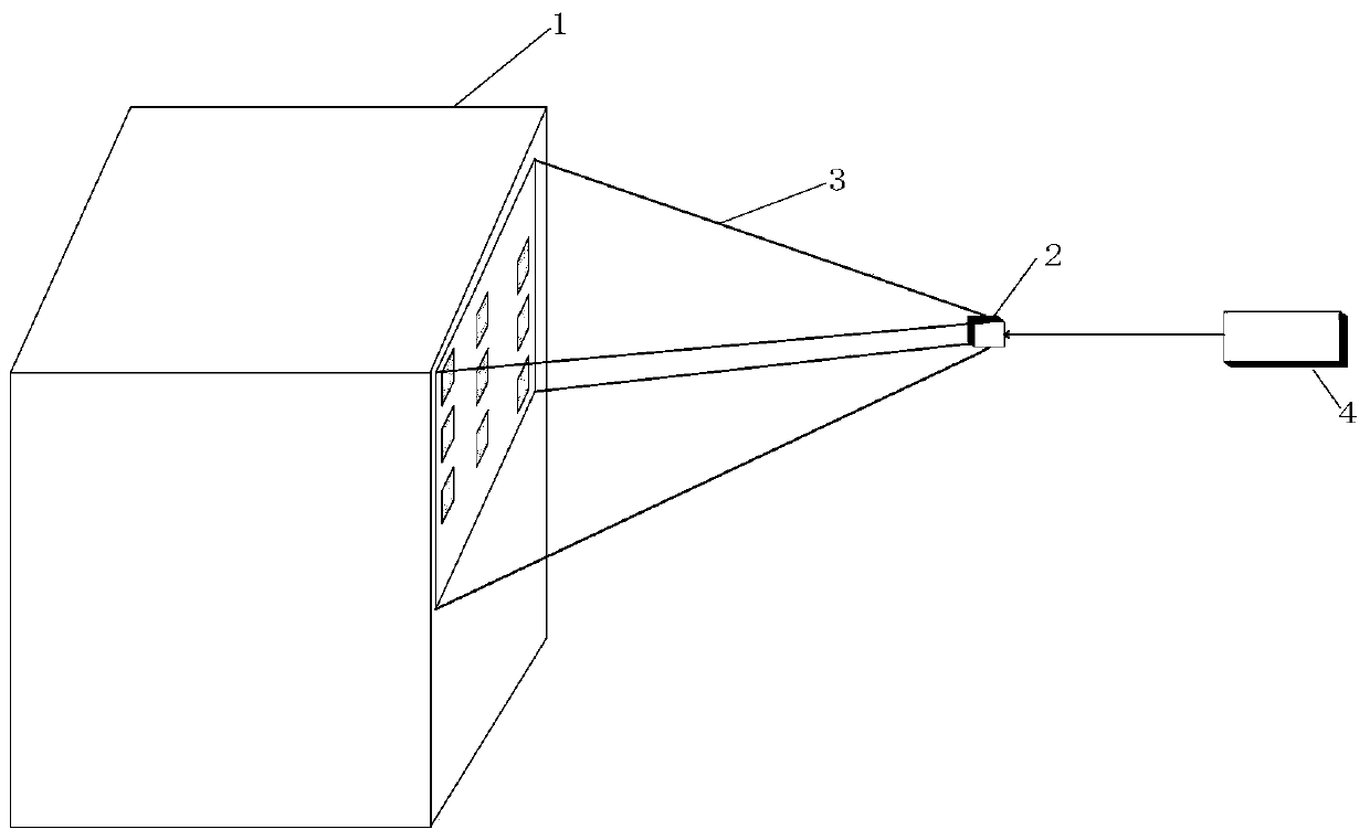
[0037]Step 1, fix the bracket on the four corners of the array radiometer 1 receiving array with screws, and the test source 2 is supported by the bracket to fix it at a certain position in the space directly in front of the array radiometer 1, so that it is located in the array radiometer 1 1. In the area in front of the team and meet the near-field conditions.

[0038] Step 2, turn on the switch of the power supply 4, so that the test source radiates a radio frequency signal with a certain bandwidth including the calibration frequency point. ...


PUM


Abstract

The invention discloses a method of calibrating amplitude and phase of an array radiometer channel and device. Radiation signals of a test source at a fixed position are received by an array, the phase of each receiving channel is changed sequentially with certain stepping in a range of 0 to 360 DEG, the rest channels remain unchanged, the power value of the receiving signal power sum varying withthe phase of a receiving channel unit is measured, the phase and the amplitude which need to be compensated by each channel unit are sequentially obtained through certain calculation and data processing, and accurate calibration on the amplitude and the phase of the array radiometer channel are completed. The method only needs to measure the power sum of the channels in the case of calibration, and in comparison with phase measurement, the realization is simple, the antenna unit and the test source remain unchanged in the case of calibration, and quick and real-time calibration can be realized easily. The whole device is simple and strong in feasibility. The calibration method and the device can eliminate mechanical errors caused by element differences of the channels and the use environment of the array radiometer, and have the advantages of being simple, practical, real-time and quick.

Description

technical field [0001] The invention relates to the technical field of system measurement and calibration, in particular to a method and device suitable for calibrating the channel amplitude and phase of an array radiometer. Background technique [0002] With the development of antenna technology and modern electronic equipment, phased arrays have been widely used. Compared with the traditional single antenna, the phased array antenna has many advantages. It can realize the detection and tracking of the specified target by adjusting the phase of each unit, but it will also cause corresponding problems. As a huge electronic system, the phased array antenna The array contains hundreds or thousands of antenna elements and corresponding channels. Due to the inconsistency in the physical characteristics and processing accuracy of the components of each channel, there is a certain deviation between the amplitude and phase of each channel and the expected, which affects the accurac...

Claims


Application Information

Patent Timeline
Patent Type & Authority Patents(China)
IPC IPC(8): G01R35/00
CPCG01R35/005
Inventor 苗俊刚胡岸勇刘凯
Owner BEIHANG UNIV
Why Eureka
Try Eureka