Supercharge Your Innovation With Domain-Expert AI Agents!

Synchronous clock feedback circuit

A feedback circuit and synchronous clock technology, applied in radio wave measurement systems, instruments, etc., can solve the problems of heavy modules, large size, and difficult implementation of radar system engineering, and achieve the effect of avoiding cost and high frequency stability.

Inactive Publication Date: 2019-03-29
SICHUAN JIUZHOU ELECTRIC GROUP
View PDF16 Cites 1 Cited by
  • Summary
  • Abstract
  • Description
  • Claims
  • Application Information

AI Technical Summary

Problems solved by technology

[0004] Although the existing clock circuit for achieving high frequency stability can meet the system requirements in terms of technical indicators, factors such as high cost, large volume, and heavy module of the atomic clock cause difficulties in the engineering realization of the radar system, and it is difficult to meet the requirements of the airborne radar system. requirements

Method used


Image

  • Synchronous clock feedback circuit
  • Synchronous clock feedback circuit
  • Synchronous clock feedback circuit

Examples


Embodiment 1

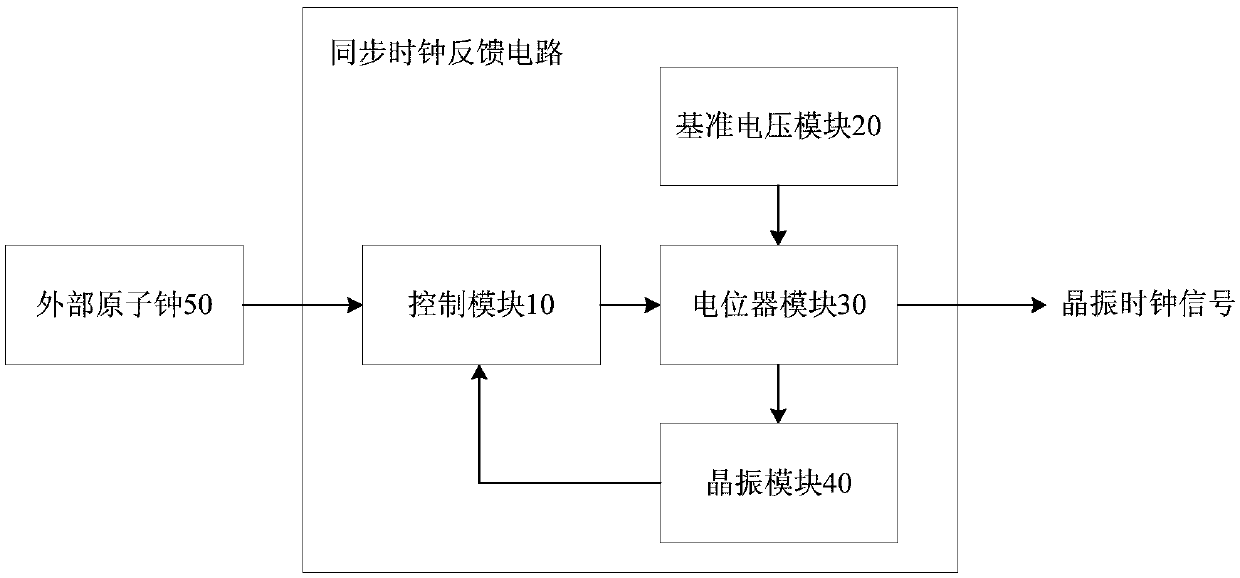
[0035] figure 2 It is a schematic diagram of the module composition of the synchronous clock feedback circuit according to Embodiment 1 of the present invention. Such as figure 2 As shown, the synchronous clock feedback circuit includes a control module 10 , a reference voltage module 20 , a potentiometer module 30 and a crystal oscillator module 40 . Wherein, the control module 10 is connected with the crystal oscillator module 40 , and the potentiometer module 30 is connected with the reference voltage module 20 , the control module 10 and the crystal oscillator module 40 .

[0036] Such as figure 2 As shown, when the crystal oscillator module 40 needs to be calibrated, the control module 10 is connected to an external atomic clock 50 . When the crystal oscillator module 40 does not need to be calibrated, the control module 10 is not connected to an external atomic clock and stops working, and only the crystal oscillator module 40 provides a crystal oscillator clock si...

Embodiment 2

[0042] Figure 4 It is a schematic diagram of a synchronous clock feedback circuit according to Embodiment 2 of the present invention. Such as Figure 4 As shown, the synchronous clock feedback circuit includes FPGA11 , reference voltage source 21 , digital potentiometer 31 and constant temperature crystal oscillator 41 . Wherein, FPGA11 is connected with constant temperature crystal oscillator 41 , digital potentiometer 31 is connected with reference voltage source 21 , FPGA11 and constant temperature crystal oscillator 41 .

[0043] When the constant temperature crystal oscillator 41 needs to be calibrated, the FPGA 11 is connected to an external atomic clock 50 . When the constant temperature crystal oscillator 41 does not need to be calibrated, the FPGA 11 is not connected to an external atomic clock and stops working, and only the constant temperature crystal oscillator 41 provides a crystal oscillator clock signal to the outside. The synchronous clock feedback circuit...


PUM


Abstract

The invention discloses a synchronous clock feedback circuit, comprising a control module, a reference voltage module, a potentiometer module and a crystal oscillator module. The control module is used for simultaneously acquiring a calibration clock signal of an external atomic clock and a crystal oscillator clock signal of the crystal oscillator module, comparing the frequency of the calibrationclock signal and the crystal oscillator clock signal, and outputting a digital control signal if the frequency of the calibration clock signal and the crystal oscillator clock signal is different until the frequency of the calibration clock signal and the crystal oscillator clock signal is the same. The potentiometer module is used for adjusting a resistance value according to a digital control signal output by the control module to adjust an analog reference voltage output by the reference voltage module, and feeding back the adjusted analog reference voltage to the crystal oscillator module, thereby realizing the frequency stability calibration of the crystal oscillator module, which can achieve high frequency stability while avoiding the influence of the high cost, large volume and heavy weight of the atomic clock on an airborne radar system.

Description

technical field [0001] The invention relates to the technical field of clock circuits, in particular to a synchronous clock feedback circuit. Background technique [0002] Frequency stability is a key technical indicator of frequency source design. The frequency stability of the frequency source directly affects the demodulation of the radar receiver. The frequency stability of the frequency source is determined by the reference crystal oscillator. Therefore, how to achieve high frequency stability is a hot research topic in frequency source design. [0003] Currently, in order to achieve high frequency stability, such as figure 1 As shown, the existing clock circuit for achieving high frequency stability is to lock an atomic clock with high frequency stability to an internal crystal oscillator with relatively high short-term stability. [0004] Although the existing clock circuit for achieving high frequency stability can meet the system requirements in terms of technic...

Claims


Application Information

Patent Timeline
IPC IPC(8): G01S7/28G01S7/40
CPCG01S7/28G01S7/4004
Inventor 罗武田殷杨光孙敏黄春燕
Owner SICHUAN JIUZHOU ELECTRIC GROUP
Features
  • R&D
  • Intellectual Property
  • Life Sciences
  • Materials
  • Tech Scout
  • Unparalleled Data Quality
  • Higher Quality Content
  • 60% Fewer Hallucinations
Learn More