
Control device for realizing fast variable polarization of electromagnetic wave

A polarization control and electromagnetic wave technology, applied in the field of target simulators, can solve problems such as destruction and inability to meet the performance requirements of P-band radar, and achieve the effect of simple principle, easy implementation and remarkable effect.

Pending Publication Date: 2019-03-29
NANJING CHANGFENG AEROSPACE ELECTRONICS SCI & TECH
View PDF3 Cites 4 Cited by
  • Summary
  • Abstract
  • Description
  • Claims
  • Application Information

AI Technical Summary

Problems solved by technology

[0003] In the traditional target simulator for target testing, the radar signal generated by the P-band radar signal source passes through the solid-state power amplifier and then directly enters the horizontally polarized antenna A and the horizontally polarized antenna B. The P-band electromagnetic wave only uses horizontal polarization. This single With the rapid development of electronic countermeasures technology, it has been unable to meet the performance requirements of P-band radar in modern warfare.
In a complex electromagnetic environment, radar without anti-jamming is not only useless, but will expose itself and even be destroyed by the enemy

Method used


Image

  • Control device for realizing fast variable polarization of electromagnetic wave
  • Control device for realizing fast variable polarization of electromagnetic wave
  • Control device for realizing fast variable polarization of electromagnetic wave

Examples


Embodiment

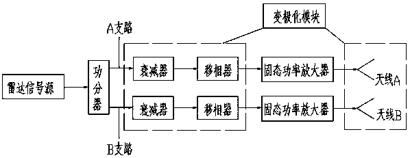
[0024] In order to achieve the function of rapidly changing polarization, two attenuators and two phase shifters are added to the traditional target simulator. The composition principle is as follows: figure 1 and figure 2 As shown, the radar signal generated by the radar signal source is divided into two paths by the power divider, one path flows through the A branch, and the other flows through the B branch. The A branch includes attenuators, phase shifters, power amplifiers and antennas connected in sequence The A and B branches include sequentially connected attenuators, phase shifters, power amplifiers, and antenna B, and antenna A and antenna B are placed orthogonally to each other at an angle of 45 degrees.

[0025] The radar signal flowing through the A branch is attenuated by the attenuator in turn, phase-shifted by the phase shifter, amplified by the power amplifier and then fed to the antenna A, and the radar signal flowing through the B branch is passed through th...


PUM


Abstract

The invention discloses a control device for realizing fast variable polarization of an electromagnetic wave. The device comprises an attenuator, a phase shifter, a power amplifier and an antenna A, wherein the attenuator, the phase shifter, the power amplifier and the antenna A are successively connected in a branched circuit A. The device further comprises an attenuator, a phase shifter, a poweramplifier and an antenna B, wherein the attenuator, the phase shifter, the power amplifier and the antenna B are successively connected in a branched circuit B. The antenna A and the antenna B are orthogonally placed in an oblique 45-DEG manner. A radar signal which is generated by a radar signal source is divided into two paths through a power divider. One path of the radar signal flows over thebranched circuit A, and the other path of the radar signal flows over the branched circuit B. The radar signal which flows over the branched circuit A successively passes the attenuator, the phase shifter and the power amplifier, and afterwards is fed into the antenna A. The radar signal which flows over the branched circuit B successively passes the attenuator, the phase shifter and the power amplifier, and afterwards is fed into the antenna B. The signal which is radiated from the antenna A and the antenna B is in a synthetic polarization state in a space. The device according to the invention can quickly realize variable polarization and can simulate modern enemy air early-warning radar electromagnetic interference and clutter interference prevention, and an electromagnetic wave fast variable polarization characteristic with improved target identification reliability.

Description

technical field [0001] The invention relates to the technical field of target simulators, in particular to a control device for realizing rapid change in polarization of electromagnetic waves. Background technique [0002] Polarization refers to the shape and handedness of the spatial trajectory formed by the endpoints of the electric field vector as a function of time during the propagation of electromagnetic waves. According to the direction of rotation of the endpoints of the electric field vector and the shape of the trajectory, polarization can usually be divided into two categories, one is linear polarization, and the direction of the electric field vector of linear polarization is fixed during the propagation process, such as horizontal polarization and Vertical polarization is a special case of linear polarization; the other type is rotational polarization. The direction of the electric field vector of rotationally polarized waves changes in rotation, and its shape i...

Claims


Application Information

Patent Timeline
IPC IPC(8): G01S7/36
CPCG01S7/36
Inventor 李正道耿波刘宏璇
Owner NANJING CHANGFENG AEROSPACE ELECTRONICS SCI & TECH
Learn More