A qam modulation signal transmission method based on array antenna
A modulated signal and array antenna technology, applied in the field of QAM modulated signal transmission, can solve the problems of great difficulty, affecting the digital pre-distortion system, and unable to solve the problem of efficient linear transmission of QAM signals, so as to improve the security performance, high efficiency and so on. The effect of linear emission and consistent working state
- Summary
- Abstract
- Description
- Claims
- Application Information
AI Technical Summary
Problems solved by technology
Method used
Image
Examples
Embodiment 1
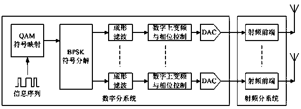
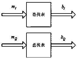
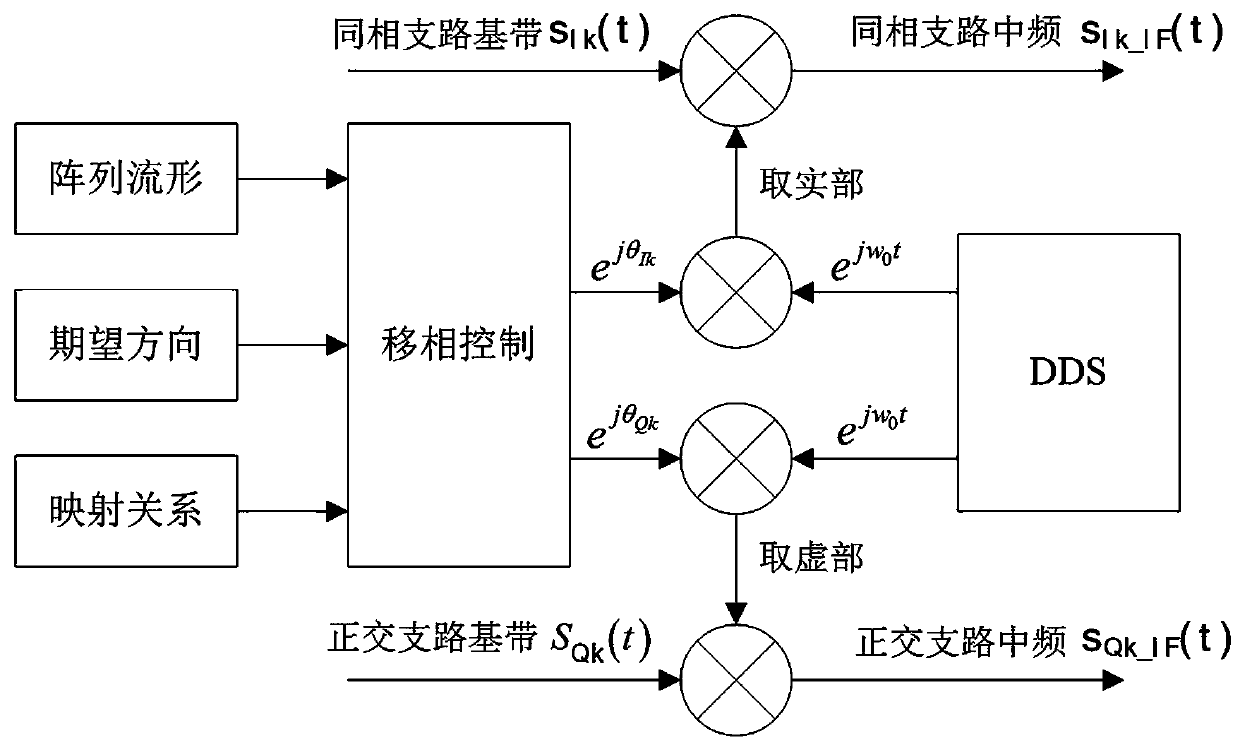
[0038] As a preferred embodiment of the present invention, with reference to the attached Figure 1-3 , this example discloses:
[0039] A method for transmitting a QAM modulated signal based on an array antenna, characterized in that: comprising the steps:
[0040] A. Perform symbol mapping on the information sequence to obtain QAM symbols;
[0041] B. Carry out BPSK symbol decomposition to the QAM symbol, and carry out antenna mapping to the BPSK symbol obtained by decomposing; The BPSK symbol obtained by decomposing includes in-phase branch BPSK symbol and orthogonal branch BPSK symbol;
[0042] C. Carry out shaping filtering to each branch BPSK symbol, obtain BPSK baseband modulation signal;
[0043] D. The BPSK baseband modulation signal of each branch passes through the digital up-conversion and phase control unit to obtain a multi-channel digital intermediate frequency modulation signal;
[0044] E. The multi-channel digital intermediate frequency modulation signal is ...
Embodiment 2
[0048] As another preferred embodiment of the present invention, with reference to the attached Figure 1-3 , this example discloses:
[0049] Realization block diagram of QAM modulation signal transmitter based on array antenna figure 1 As shown, it is mainly composed of digital subsystem, radio frequency subsystem and array antenna. Its hardware structure is the same as that of the traditional digital array transmitter, the difference lies in the part of the digital subsystem. What each antenna unit radiation in the traditional digital array transmitter is a QAM modulation signal, by controlling the phase of each antenna unit signal, the signal power in the desired direction is maximized; what each antenna unit radiation is an independent BPSK modulation signal in the present invention, By controlling the phase of each antenna unit signal, a QAM modulated signal is generated in the desired direction, and the modulated constellation diagram in other directions will produce ...
Embodiment 3
[0070] As another preferred embodiment of the present invention, with reference to the attached Figure 1-3 , this example discloses:
[0071] In this embodiment, taking a 16QAM modulated signal transmitter based on a six-element uniform linear array antenna as an example, the implementation steps are as follows:
[0072] BPSK Symbol Decomposition and Antenna Mapping
[0073] Decompose the 16QAM signal into 6 BPSK symbols as follows:
[0074] m I / m Q
b I1 / b I2
b I2 / b Q2
b I3 / b Q3
-3 -1 -1 -1 -1 1 -1 -1 1 1 1 -1 3 1 1 1
[0075] Randomly arrange the 6 BPSK symbols and correspond to the 6 antenna units one by one, with a total of A mapping relationship can be randomly selected in the specific implementation.
[0076] 2) Phase control
[0077] For a six-element uniform linear array, set the array element spacing as d and the carrier wavelength as λ. Then the array manifold vector is a column vector...
PUM
 Abstract
Description
Claims
Application Information
 - R&D
- Intellectual Property
- Life Sciences
- Materials
- Tech Scout
- Unparalleled Data Quality
- Higher Quality Content
- 60% Fewer Hallucinations
Browse by: Latest US Patents, China's latest patents, Technical Efficacy Thesaurus, Application Domain, Technology Topic, Popular Technical Reports.
© 2025 PatSnap. All rights reserved.Legal|Privacy policy|Modern Slavery Act Transparency Statement|Sitemap|About US| Contact US: help@patsnap.com


