
Method for adjusting grating line parallel to line source

A line light source, grating engraving technology, applied in the field of spectral analysis, can solve the problems of light intensity, the device is not easy to operate, and it is difficult to clearly see the stripes, etc., to achieve the effect of simple operation and high accuracy

Inactive Publication Date: 2019-03-29
天津国阳科技发展有限公司
View PDF6 Cites 0 Cited by
  • Summary
  • Abstract
  • Description
  • Claims
  • Application Information

AI Technical Summary

Problems solved by technology

[0002] The traditional device for adjusting the parallelism between the grating lines and the line light source is to irradiate the light emitted by the slit onto the grating, and then diffract to the photodetector for adjustment (the device is complicated and difficult to operate). Because the light emitted by the slit is weak, it is very difficult for the naked eye to adjust. It is difficult to clearly see the fringes diffracted from the grating, and the light detection element is needed, and the light intensity of the external environment is weak, and the adjustment (test) process is easily disturbed by the external environment

Method used


Image

  • Method for adjusting grating line parallel to line source
  • Method for adjusting grating line parallel to line source
  • Method for adjusting grating line parallel to line source

Examples


Embodiment Construction

[0019] In order to understand the above-mentioned purpose, features and advantages of the present invention more clearly, the present invention will be further described in detail below in conjunction with the accompanying drawings and specific embodiments.

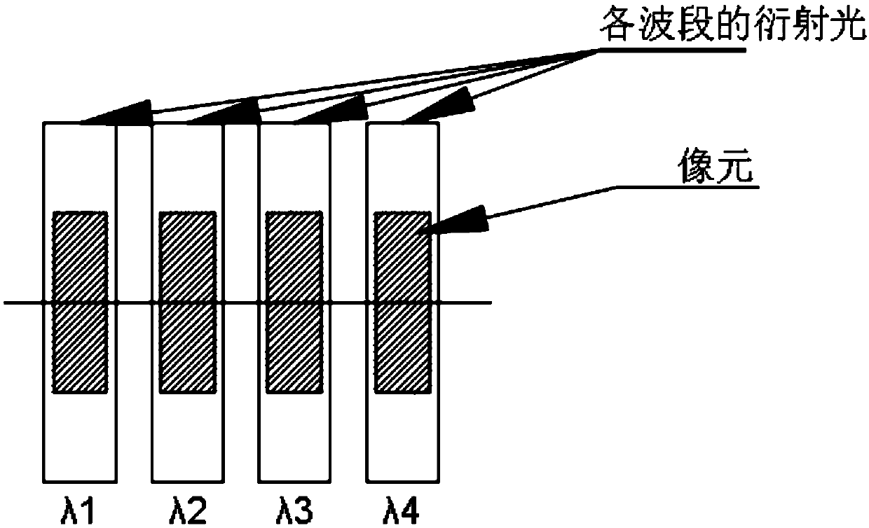
[0020] When the incident light is perpendicular to the grating surface, when the grating lines are not parallel to the line light source, the position of the 0th-order diffraction line remains unchanged, and the +1-order and -1-order diffraction spots are shifted upward and downward, respectively. , there is a phenomenon of unequal height, and it is slightly closer to the central zero-order diffraction spot. When the staggered angle between the grating reticle and the line light source increases, the offset distance of the +1 order and -1 order diffraction spots in the up and down direction Significantly increased. Generally, the linear array CCD is used to analyze the optical signal for spectral acquisition. The linear a...


PUM


Abstract

The invention provides a method for adjusting a grating line parallel to a line source, and relates to the technical field of a spectrum analysis. The method comprises the following steps of: equipping with a monochromatic light source capable of adjusting an angle of an exit light and fixing on a platform; equipping with a standard grating bonded to a grating frame and placing on the platform, wherein the standard grating line is parallel to the line source emitted by the monochromatic source; adjusting the monochromatic light source to illuminate the surface of the standard grating, and throwing a diffraction pattern onto a receiving screen; fixing the angle of the monochromatic light source, and marking on at least two diffraction spots of the diffraction pattern; putting a measured grating into an unbonded grating frame and replacing the standard grating; and rotating the measured grating until the diffraction spot of the measured grating is on the same line as the diffraction spotof the standard grating. The method does not need to use light detecting elements, does not need to operate in a dark environment, and has the characteristics of simple operation, high speed, high accuracy and the like.

Description

technical field [0001] The invention relates to the technical field of spectral analysis, in particular to a method for adjusting grating lines parallel to a line light source. Background technique [0002] The traditional device for adjusting the parallelism between the grating lines and the line light source is to irradiate the light emitted by the slit onto the grating, and then diffract to the photodetector for adjustment (the device is complicated and difficult to operate). Because the light emitted by the slit is weak, it is very difficult for the naked eye to adjust. It is difficult to clearly see the fringes diffracted from the grating, which requires the use of photodetection elements, and the light intensity of the external environment is weak, and the adjustment (test) process is easily disturbed by the external environment. Contents of the invention [0003] The present invention aims to solve at least one of the technical problems existing in the above-mention...

Claims


Application Information

Patent Timeline
IPC IPC(8): G02B7/00G02B27/62
CPCG02B7/00G02B27/62
Inventor 綦振华郭萌付泽禛
Owner 天津国阳科技发展有限公司
Learn More