
A method for optimizing the layout of oil injection lubrication nozzles ofa helical bevel gear for an aerospace

A spiral bevel gear, layout optimization technology, applied in the field of aviation spiral bevel gear oil injection lubrication nozzle layout optimization design, to achieve fast and efficient lubrication effect and improve the effect of lubrication effect

Active Publication Date: 2019-03-29
CENT SOUTH UNIV
View PDF4 Cites 4 Cited by
  • Summary
  • Abstract
  • Description
  • Claims
  • Application Information

AI Technical Summary

Problems solved by technology

[0004] The orientation parameter of the nozzle oil injection has a direct impact on whether the lubricating oil can directly enter the meshing part of the gear teeth. The design of the traditional spiral bevel gear oil injection lubrication nozzle is usually placed according to experience. However, in actual work, different engines or gears in different positions of the engine The settings will not be exactly the same, making it difficult to arrive at the best nozzle settings based on experience alone

Method used


Image

  • A method for optimizing the layout of oil injection lubrication nozzles ofa helical bevel gear for an aerospace
  • A method for optimizing the layout of oil injection lubrication nozzles ofa helical bevel gear for an aerospace
  • A method for optimizing the layout of oil injection lubrication nozzles ofa helical bevel gear for an aerospace

Examples


Embodiment Construction

[0048] The present invention will be described in further detail below in conjunction with the accompanying drawings and formulas.

[0049] In order to make the object, technical solution and advantages of the present invention clearer, the present invention will be further described in detail below in conjunction with the accompanying drawings and specific embodiments. It should be understood that the specific embodiments described here are only used to explain the present invention, and are not intended to limit the present invention.

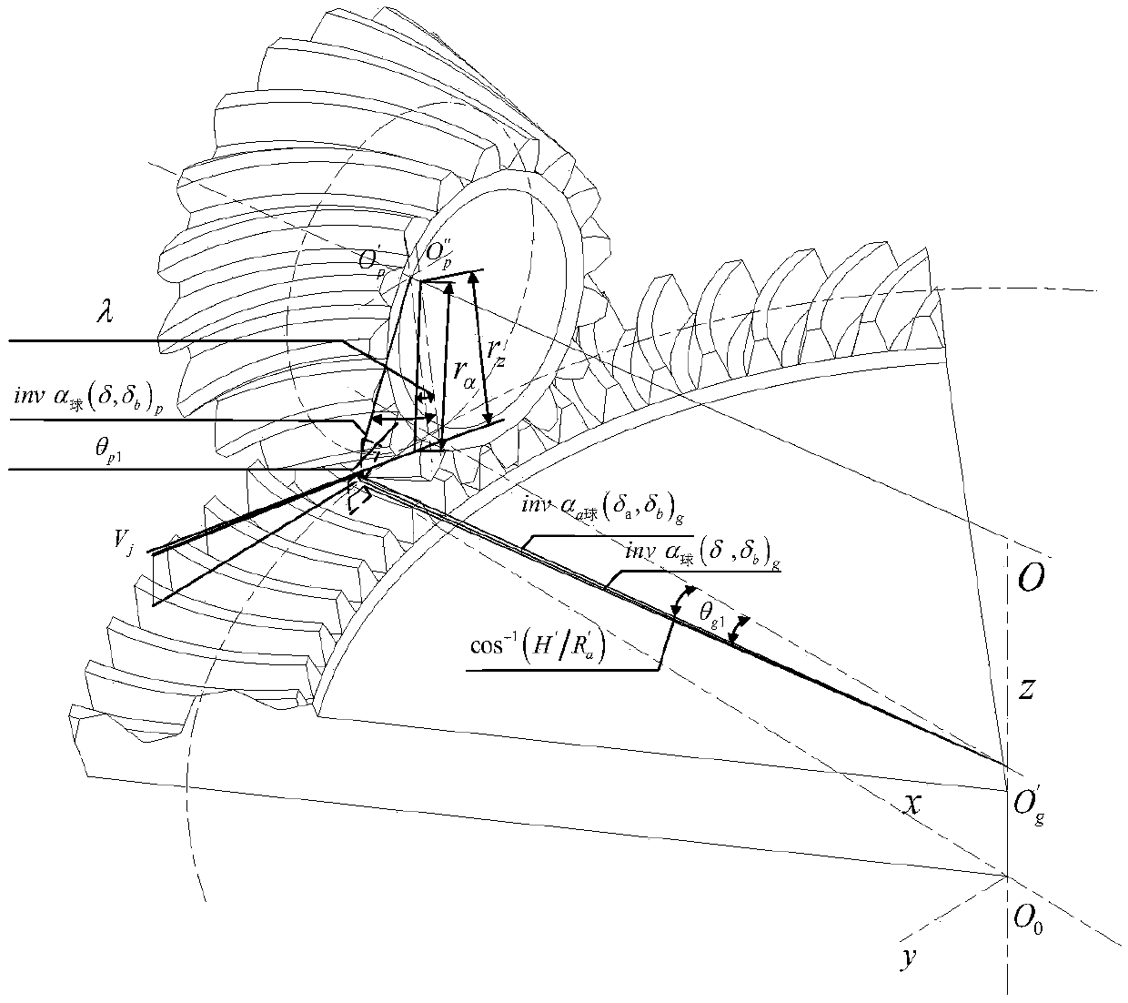
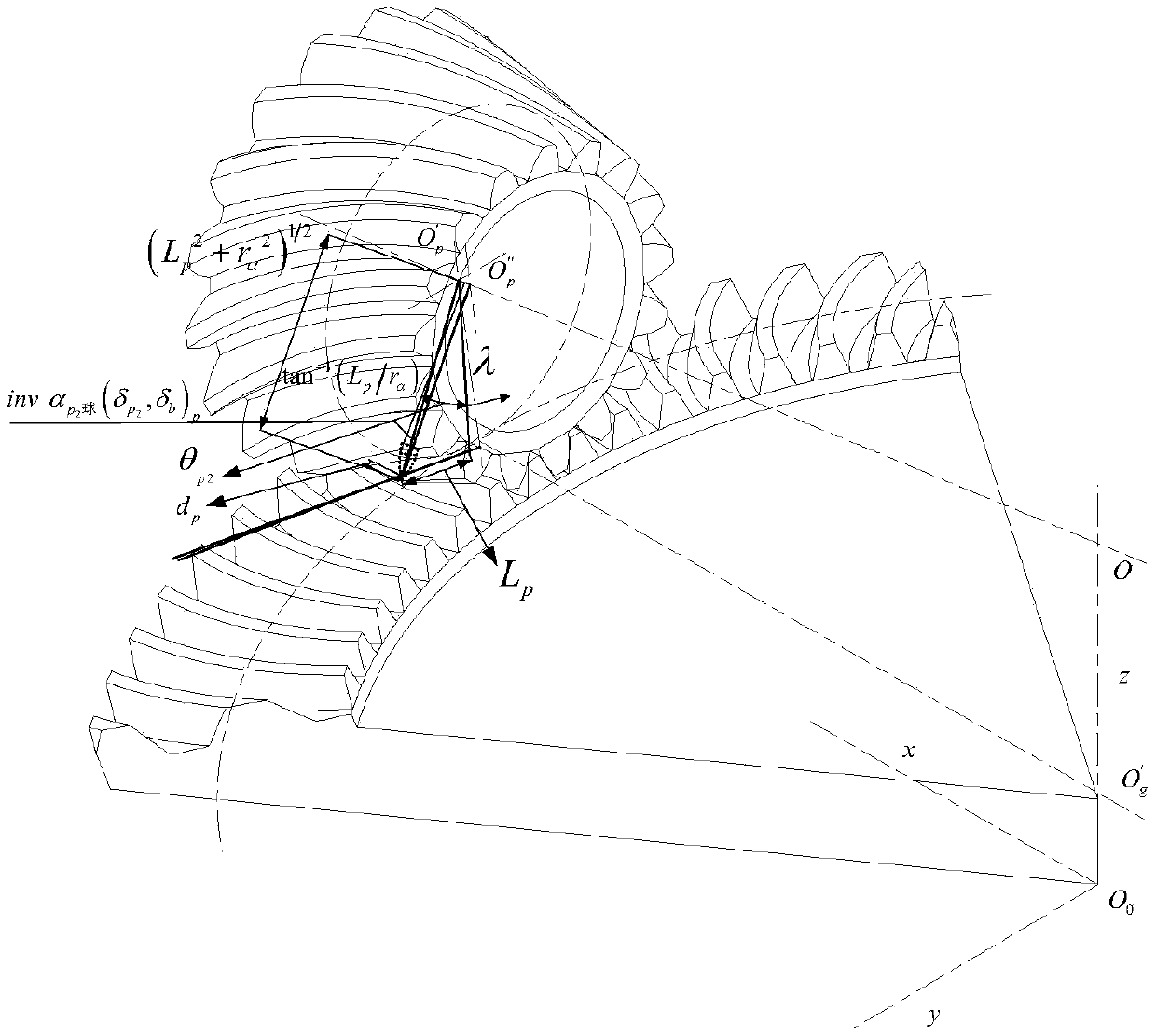
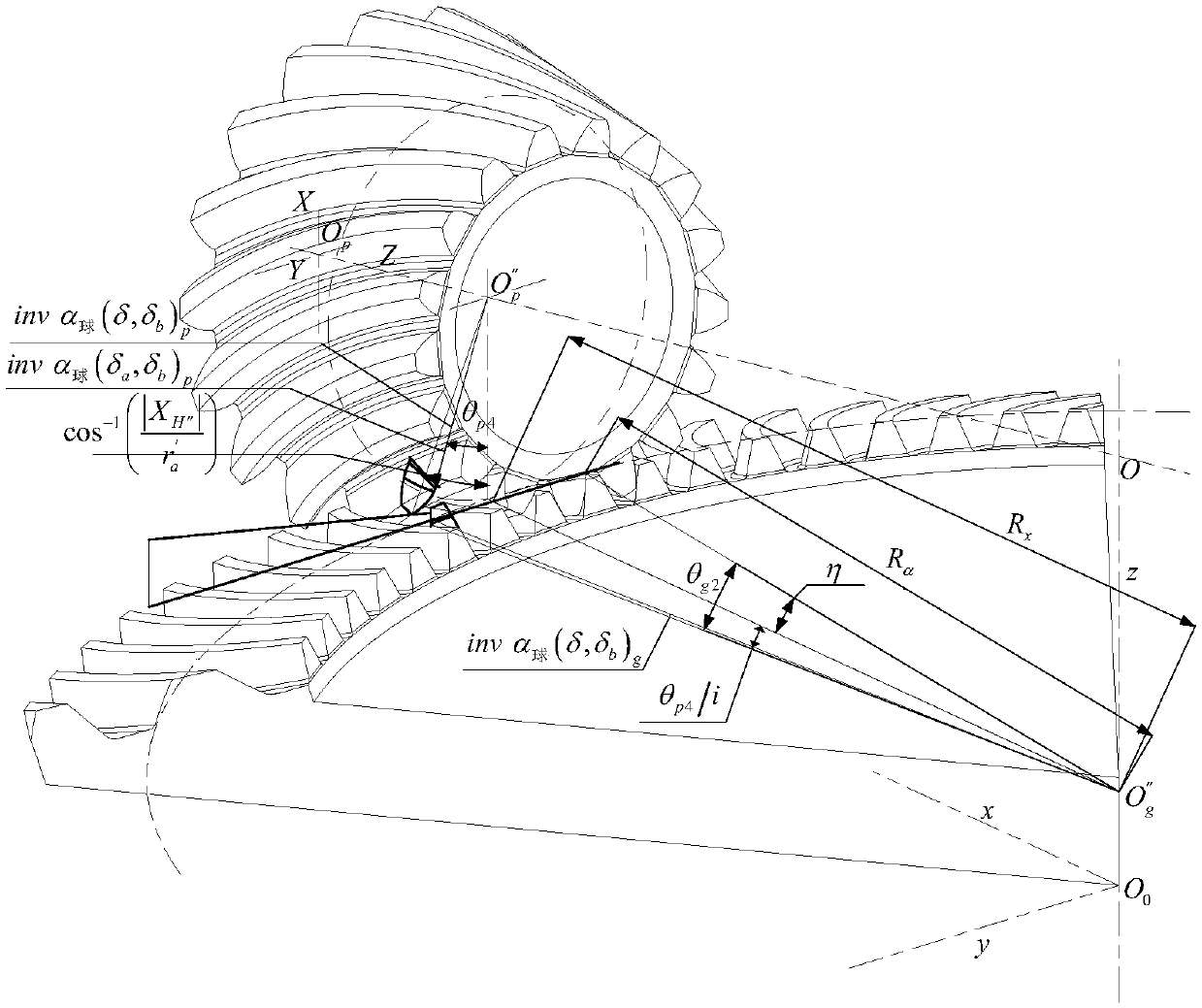
[0050] see figure 1 , this specific embodiment adopts the following technical scheme: first calculate the value of the impact depth of the lubricating oil sprayed on the tooth surface of the large spiral bevel gear and the small spiral bevel gear meshing with each other, and then based on the greater the impact depth, the better the gear lubrication effect In principle, the lubrication effect under different nozzle layouts can be obtained fr...


PUM


Abstract

The invention discloses a method for optimizing the layout of oil injection lubrication nozzles of a helical bevel gear for an aerospace. The lubricating effect of gear can be judged by calculating the impact depth of lubricating oil sprayed on the surface of gear teeth, so as to optimize the layout of nozzle parameters, The calculation steps of the mathematical model are as follows: the spatial relationship between the involute and the involute of the spiral bevel gear, and the geometrical operation are used to obtain the spatial position of the large and small gears and the position change of the oil jet line in a period of time (the relationship between the initial time spiral bevel gear pair and the jet line is shown in the drawing) As shown in the figure, at the same time, according to the time that the gear meshing angle is equal to the jet injection time, the impact depth of the lubricating oil on the large and small gears is obtained.The method for calculating the mathematicalmodel of the impact depth is simple and can improve the oil injection lubrication performance and the effect of the gear.

Description

technical field [0001] The invention relates to an optimization design method for the layout of an aviation spiral bevel gear oil injection lubrication nozzle. Background technique [0002] The working environment of aviation gears is high-speed conditions, and oil injection lubrication is usually used. However, due to the small meshing gap during the meshing process of the gear teeth, the high-speed rotating gears will block the jet flow, which leads to The gear teeth may run at high speed in the state of lack of oil or even no oil, which greatly affects the service life of the gear. Therefore, it is very important to explore better oil injection methods to obtain better lubrication effects. [0003] The main working environment of aero-engine gears is high speed and heavy load. In this case, the main failure modes are: scratches, pitting, plastic deformation, tooth surface gluing, and gear expansion caused by high temperature, resulting in seizure. To avoid these failures...

Claims


Application Information

Patent Timeline
Patent Type & Authority Applications(China)
IPC IPC(8): G06F17/50
CPCG06F30/17Y02T90/00
Inventor 戴瑜朱湘马飞跃吴伟贾继富
Owner CENT SOUTH UNIV
Learn More