Purging joint device and purging system

A joint device and purging gas technology, applied in electrical components, semiconductor/solid-state device manufacturing, circuits, etc., to avoid waste of resources

Active Publication Date: 2019-03-29
SHANGHAI HUALI MICROELECTRONICS CORP
View PDF3 Cites 1 Cited by
  • Summary
  • Abstract
  • Description
  • Claims
  • Application Information

AI Technical Summary

Problems solved by technology

[0004] The purpose of this application is to provide a purge joint device to solve the problem in the prior art that the exhaust pipe needs to be removed first and then cleaned

Method used


Image

  • Purging joint device and purging system
  • Purging joint device and purging system
  • Purging joint device and purging system

Examples


Embodiment 1

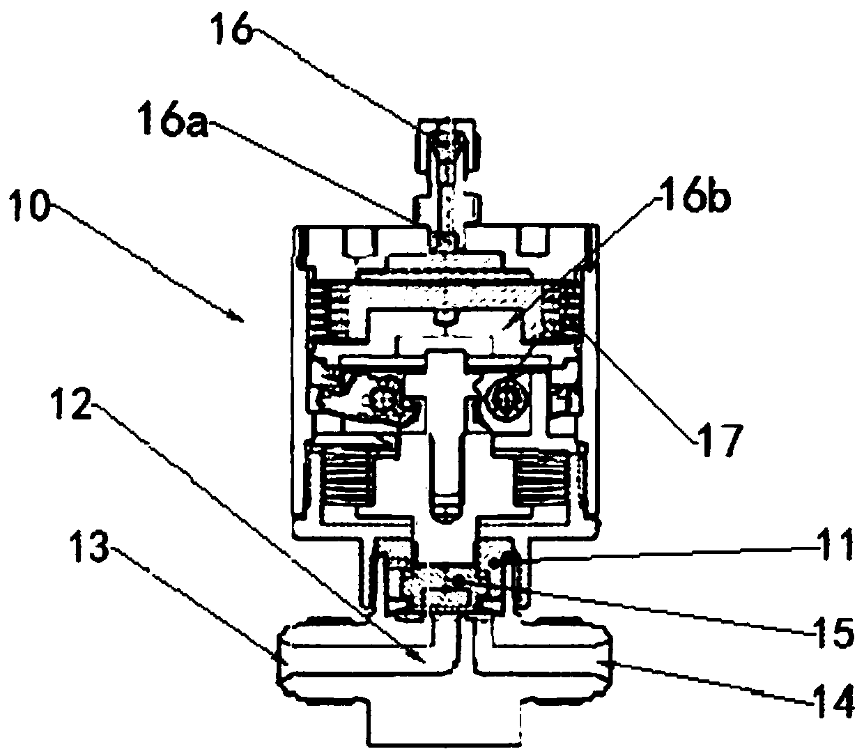
[0033] figure 1 It is a schematic diagram of a purge joint device in the embodiment of the present application.

[0034] refer to figure 1 , the present embodiment provides a purge joint device 10, comprising: a housing 11, an air passage 12, a piston 15 and a switch 16; the air passage 12 is arranged in the housing 11, wherein one end of the air passage 12 It is the purge gas inlet 13, which is connected to a purge gas source 30, and the other end of the gas channel 12 is the purge gas outlet 14, and the purge gas outlet 14 is 14 is connected with a device 20 to be purged; the piston 15 is movably arranged in the housing 11 for opening or blocking the air passage 12, and the switch 16 is connected with the piston 15 for It is used to control the piston 15 to block or open the air passage 12 .

[0035] The switch 16 is a gas-driven switch 16, the switch 16 includes a stopper 16b, the stopper 16b is provided with a driving gas interface 16a connected to a driving gas source,...

Embodiment 2

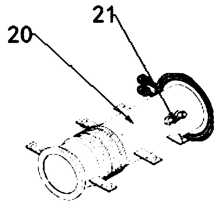
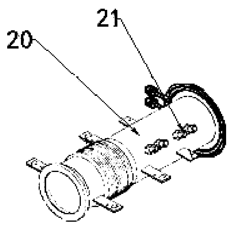
[0040] figure 2 is a schematic diagram of a device to be purged in the embodiment of the present application, image 3 is a schematic diagram of another device to be purged according to the embodiment of the present application, Figure 4 It is a schematic diagram of a purging system in the embodiment of the present application.

[0041] On the other hand, this embodiment provides a purging system, see Figure 4 , the purging system includes a purge gas source 30, a gas flow controller 40, a purge joint device 10 and a device to be purged 20; the purge gas source 30, the gas flow controller 40 and the purge The purge joint devices 10 are connected to each other through gas pipelines, and one end of the gas flow controller 40 is connected to the purge joint device 10, so as to conduct the purge gas source 30 passing into the device 20 to be purged. Flow control, so as to adjust the pressure of the purge gas source 30 in the pipeline, can rationally use the purge gas source ...


PUM


Abstract

The invention provides a purging joint device and a purging system. When a to-be-purged device needs purging, a gas passage is opened by a piston under the control of a switch to automatically purge the to-be-purged device. Thus, there is no need to manually disassemble and clean the to-be-purged device, the consumption of manpower can be avoided, and the operation time of the to-be-purged devicecan be increased. When the to-be-purged device does not need purging, the gas passage is plugged by the piston under the control of the switch, so that a purging gas source cannot enter the to-be-purged device, and no waste of the purging gas source is caused.

Description

technical field [0001] The present application relates to the field of semiconductor preparation, in particular to a purging joint device and a purging system. Background technique [0002] With the continuous development of semiconductor technology, wafer manufacturing as a basic process has received more and more attention. The reaction exhaust gas in the wafer manufacturing process is discharged from the tail of the furnace through the exhaust pipe connected to the furnace of the atomic layer deposition equipment. Since the exhaust pipe is very long, the exhaust gas passes through the exhaust pipe at the furnace tail and is away from the discharge section in the furnace. When the discharge section of the exhaust pipe is far away from the furnace, the temperature of the exhaust gas will drop suddenly, and the exhaust gas will react with the surrounding water vapor to generate a lot of particles. These particles will gather on the inner wall of the exhaust pipe, and the con...

Claims


Application Information

Patent Timeline
Patent Type & Authority Applications(China)
IPC IPC(8): H01L21/67
CPCH01L21/67017H01L21/67034
Inventor 佘广超敖海林魏巍
Owner SHANGHAI HUALI MICROELECTRONICS CORP
Why Eureka
Try Eureka