Anti-rotation bolt assembly for conductive use

A bolt assembly and application technology, applied in the field of anti-rotation bolt assemblies, to achieve the effects of easy processing, high strength and toughness, and simple structure

Active Publication Date: 2019-03-29
北京航天微电科技有限公司
View PDF5 Cites 3 Cited by
  • Summary
  • Abstract
  • Description
  • Claims
  • Application Information

AI Technical Summary

Problems solved by technology

However, when the user tightens the nut, as the tightening torque increases, the bolt rotates with the nut at the same time, causing the co...

Method used


Image

  • Anti-rotation bolt assembly for conductive use
  • Anti-rotation bolt assembly for conductive use
  • Anti-rotation bolt assembly for conductive use

Examples


Embodiment 1

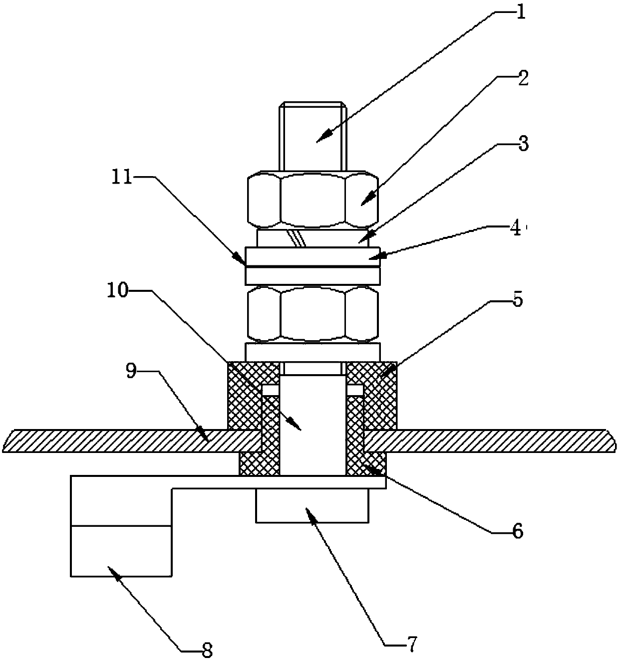
[0034] The invention provides an anti-rotation bolt assembly for conductive purposes, comprising:

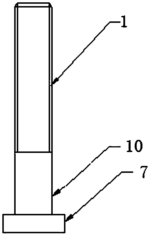
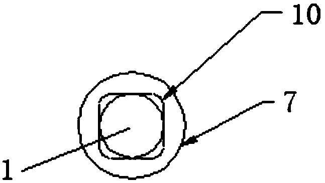
[0035] Bolt, described bolt comprises bolt cap 7, square screw rod 10 and round screw rod 1 successively from bottom to top, described bolt cap 7, square screw rod 10 and round screw rod 1 are fixedly connected or integrally formed, and described round screw rod The outer surface of 1 is provided with threads;

[0036] A crimping assembly, the crimping assembly is sleeved on the circular screw 1 and threadedly connected with the circular screw 1;

[0037] An insulating assembly, the insulating assembly is sleeved on the square screw 10, and is used to realize the insulation between the bolt and the housing 9;

[0038] A connection terminal, the connection terminal is provided with an inner hole suitable for the square screw 10 , the inner control is sleeved on the lower part of the square screw 10 and is in contact with the bolt cap 7 .

[0039] Further, the wire crimping asse...

Embodiment 2

[0045] The invention provides an anti-rotation bolt assembly for conductive purposes, comprising:

[0046] Bolt, described bolt comprises bolt cap 7, square screw rod 10 and round screw rod 1 successively from bottom to top, described bolt cap 7, square screw rod 10 and round screw rod 1 are fixedly connected or integrally formed, and described round screw rod The outer surface of 1 is provided with threads;

[0047] A crimping assembly, the crimping assembly is sleeved on the circular screw 1 and threadedly connected with the circular screw 1;

[0048] An insulating assembly, the insulating assembly is sleeved on the square screw 10, and is used to realize the insulation between the bolt and the housing 9;

[0049] A connection terminal, the connection terminal is provided with an inner hole suitable for the square screw 10 , the inner control is sleeved on the lower part of the square screw 10 and is in contact with the bolt cap 7 .

[0050] Further, the wire crimping asse...


PUM


Abstract

The invention relates to an anti-rotation bolt assembly for electric conduction, which comprises a bolt, which sequentially comprises a bolt cap, a square screw rod and a round screw rod from bottom to top, wherein the bolt cap, the square screw rod and the round screw rod are fixedly connected or integrally formed, and the outer surface of the round screw rod is provided with a thread. The anti-rotation bolt assembly further comprises a wire pressing assembly connected to the circular screw rod in a sleeving manner and being in threaded connection with the circular screw rod; an insulation assembly, wherein the square screw rod is sleeved with the insulation assembly for achieving insulation between the bolt and the shell; and wiring terminal provided with an inner hole matched with the square screw, and the inner control sleeve is connected to the lower portion of the square screw in a sleeved mode and makes contact with the bolt cap. The anti-rotation bolt assembly used for electricconduction and the using method thereof are disclosed. The anti-rotation bolt assembly is easy to disassemble and assemble, simple in structure, and is stable and reliable.

Description

technical field [0001] The invention relates to the field of equipment accessories, in particular to an anti-rotation bolt assembly for conducting electricity. Background technique [0002] In EMI filters and power filters, the input and output ports usually have the following methods: connectors, insulator leads, bolt leads, etc. The bolt lead method is mechanically fixed by nuts, which not only ensures firm wiring contact, but also is easy to install and has high reliability. Therefore, the bolt lead method is widely used in the military field. [0003] The bolt lead method is mainly to conduct electricity through the bolt, use insulating material to isolate the bolt from the shell at the contact position between the bolt and the shell, solder the copper terminal and the bolt together inside the shell, and then weld the wire to the copper terminal; The wires are crimped together on the outside of the housing through flat spring washers, nuts and bolts. However, when the...

Claims


Application Information

Patent Timeline
IPC IPC(8): H01R4/30H01R4/58H01R9/00H01R9/22H01R11/05H01R11/11
CPCH01R4/30H01R4/58H01R9/00H01R9/223H01R11/05H01R11/11
Inventor 杨子森潘雄文张中元李琦
Owner 北京航天微电科技有限公司
Why Eureka
Try Eureka