Bootstrap capacitor charging control device and control method for permanent-magnet synchronous motor

A permanent magnet synchronous motor, bootstrap capacitor technology, applied in the direction of motor control, AC motor control, control system, etc., can solve the problem of the motor controller PCB is not practical, can not drive the motor to run, increase production costs, etc., to avoid time waste, ensure normal operation, and ensure the effect of working reliability

Inactive Publication Date: 2019-03-29
东莞市深鹏电子有限公司
View PDF6 Cites 1 Cited by
  • Summary
  • Abstract
  • Description
  • Claims
  • Application Information

AI Technical Summary

Problems solved by technology

[0004] For example, on December 23, 2015, the China Intellectual Property Office published the invention patent of "a brushless motor bootstrap capacitor intelligent charging device and method" with the announcement number CN105186936A. The technical solution of this patent solves the above technical problems. However, it is necessary to increase the design of the external hardware detection circuit. This solution not only increases the production cost, but also is not practical for the PCB in the motor controller. At the same time, it cannot avoid the excessive charging current of the drive circuit during the charging process of the bootstrap capacitor. Trigger protection or damage electrical components, resulting in motor damage
[0005] On June 23, 2010, the China Intellectual Property Office published the "H-bridge circuit with energy supplementary circuit and its control method" with the announcement number CN101753007B. Although the technical solution of this patent can be detected by the H-bridge circuit with a single bridge arm structure The voltage drop across the bootstrap capacitor realizes the detection of the charging saturation of the bootstrap capacitor, that is, adding a voltage detection circuit to detect the voltage drop across the bootstrap capacitor realizes the detection of the charging saturation of the bootstrap capacitor, and compares it with the reference voltage built by the hardware. Adjust the turn-on duty cycle to solve the insufficient voltage of the bootstrap capacitor, use the auxiliary circuit in the technical solution to provide energy supplement for the bootstrap circuit, ensure that the drive circuit drives the switching power supply to work, but cannot drive the motor to run, but cannot avoid driving The charging current of the circuit is too large during the charging process of the bootstrap capacitor, which may accidentally trigger the protection or damage the electrical components, resulting in damage to the motor

Method used


Image

  • Bootstrap capacitor charging control device and control method for permanent-magnet synchronous motor
  • Bootstrap capacitor charging control device and control method for permanent-magnet synchronous motor
  • Bootstrap capacitor charging control device and control method for permanent-magnet synchronous motor

Examples


Embodiment Construction

[0046] In order to make the object, technical solution and technical effect of the present invention clearer, the present invention will be further described below in conjunction with specific embodiments. It should be understood that the specific embodiments described here are only used to explain the present invention, not to limit the present invention.

[0047] It should be noted that when an element is referred to as being “disposed on or fixed on” another element, it may be directly on the other element or there may be an intervening element. When an element is referred to as being "connected to" another element, it can be directly connected to the other element or intervening elements may also be present. The terms "vertical", "horizontal", "left", "right", "unit", "module" and similar expressions are used herein for the purpose of description only and do not represent the only embodiment.

[0048] Unless otherwise defined, all technical and scientific terms used herei...


PUM


Abstract

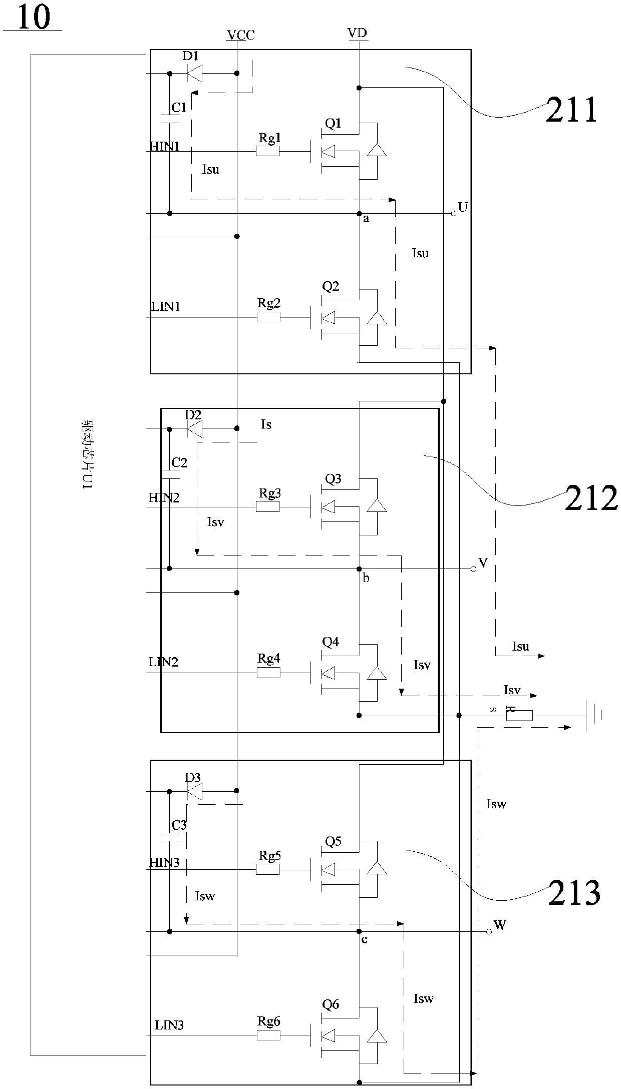
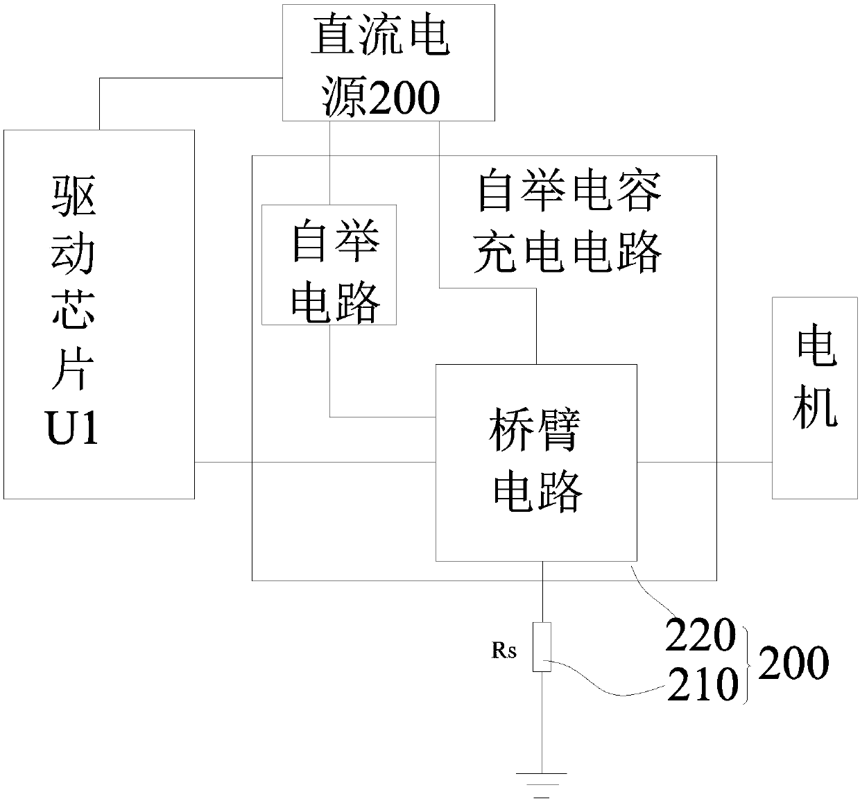
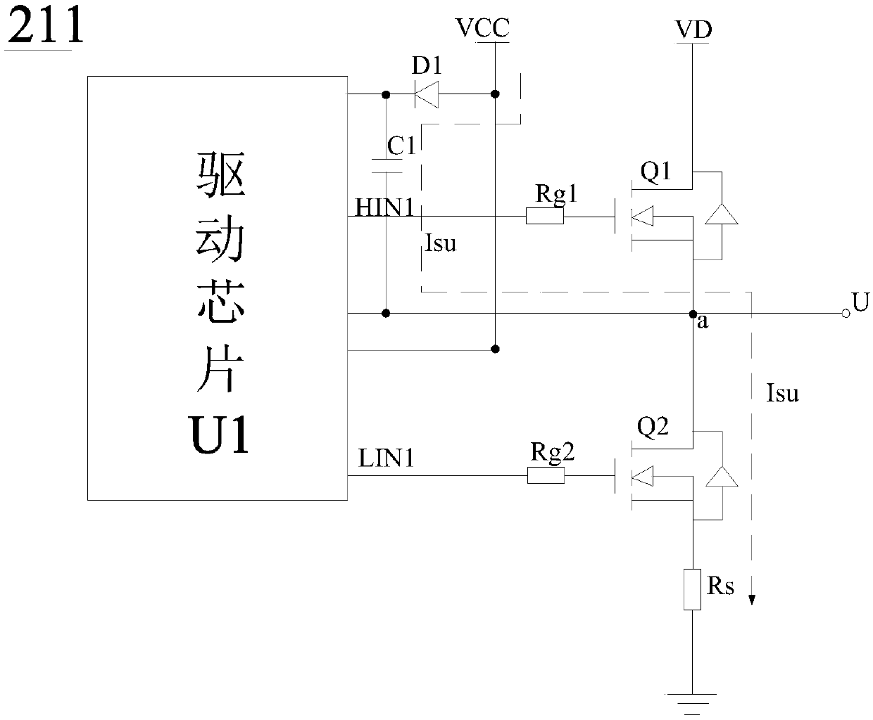
The invention relates to a bootstrap capacitor charging control device for a permanent-magnet synchronous motor, wherein the bootstrap capacitor charging control device is applied to a direct-currentmotor or a three-phase inverter power supply. The bootstrap capacitor charging control device comprises a direct-current power source and a three-phase bridge arm driving circuit. The three-phase bridge arm driving circuit includes U-phase, V-phase, and W-phase driving circuits connected in parallel and a current sampling circuit. A sampling resistor detects a bus current during the bootstrap capacitor charging process by each phase; a bus current for charging each phase is determined; the bus current for charging each phase is compared with a set current for starting each phase; first switchelements and second switch elements in the driving circuits are controlled to be in conduction one by one according to a U-phase, V-phase, and a W-phase sequence; and thus respective bootstrap capacitors are charged to drive the motor to work. According to the control device, the hardware resources are simplified; the working reliability of the bootstrap capacitor is guaranteed; the normal operation of the motor is ensured; and time wasting during the bootstrap capacitor charging process and motor damages caused by too heavy charging currents are avoided.

Description

technical field [0001] The present invention relates to the technical field of permanent magnet synchronous motors, in particular to a permanent magnet synchronous motor bootstrap capacitor charging control device, and also relates to a bootstrap capacitor based on the permanent magnet synchronous motor bootstrap capacitor charging control device charging control method. Background technique [0002] The permanent magnet synchronous motor is a synchronous motor that is excited by a permanent magnet to generate a synchronous rotating magnetic field. The permanent magnet acts as a rotor to generate a rotating magnetic field. The three-phase stator winding reacts through the armature under the action of the rotating magnetic field to induce a three-phase symmetrical current. The DC permanent magnet synchronous motor has the characteristics of high power density, high efficiency, small size and simple structure. Especially after the vector sensorless control scheme is used, for ...

Claims


Application Information

Patent Timeline
Patent Type & Authority Applications(China)
IPC IPC(8): H02P23/00H02P25/022H02P27/06
CPCH02P23/00H02P25/022H02P27/06H02P2205/01
Inventor 孙家广黄志飞
Owner 东莞市深鹏电子有限公司
Why Eureka
Try Eureka