Detector geometric correction phantom and correction method

A geometric correction and detector technology, applied in the field of radiation imaging, which can solve the problems of unrealistic performance of detector images, high inconsistency, and too large data, and achieve the effect of satisfying high-quality image quality.

Active Publication Date: 2019-04-02
NANOVISION TECHNOLOGY (BEIJING) CO LTD
View PDF13 Cites 4 Cited by
  • Summary
  • Abstract
  • Description
  • Claims
  • Application Information

AI Technical Summary

Problems solved by technology

[0003] Due to manufacturing and assembly tolerances, gaps between adjacent detector chips are unavoidable (e.g. figure 2 shown), the height is inconsistent (such as image 3 shown) and the rotation of the detector chip module itself (such as Figure 4 Shown), the data of these problems are too large will cause the collected detector image can not truly represent the information of the measured object

Method used


Image

  • Detector geometric correction phantom and correction method
  • Detector geometric correction phantom and correction method
  • Detector geometric correction phantom and correction method

Examples


Embodiment Construction

[0047] The technical content of the present invention will be further described in detail below in conjunction with the accompanying drawings and specific embodiments.

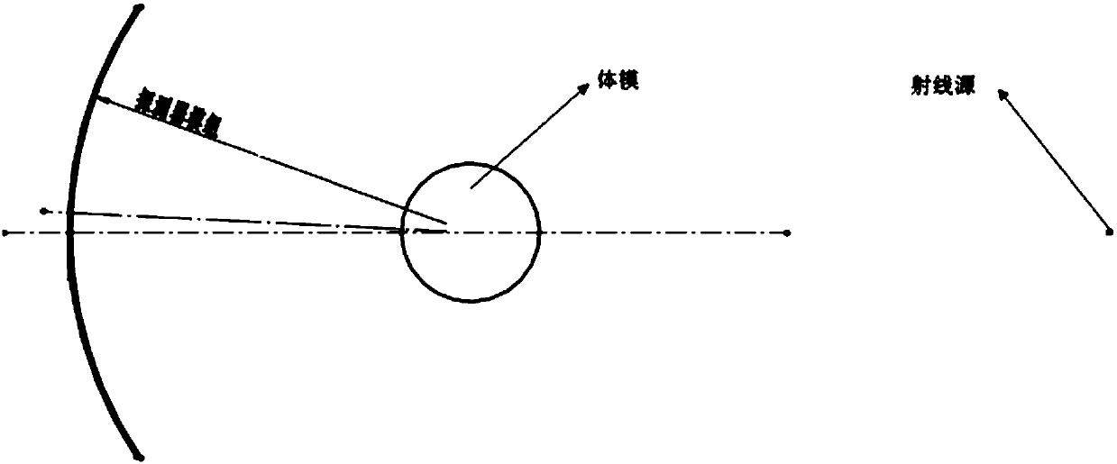
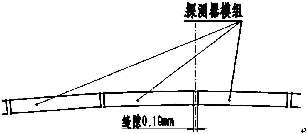
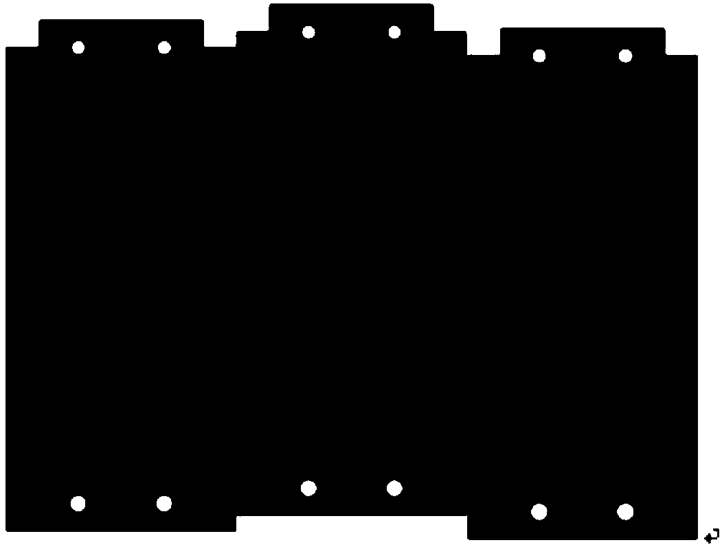
[0048] Such as Figure 5 and Figure 6 As shown, the detector geometric correction phantom provided by the present invention includes a geometric correction phantom substrate 1, and a circular hole array consisting of several rows of transverse circular holes and longitudinal circular holes of the same size is arranged on the geometric correction phantom substrate 1 2; where the spacing between adjacent circular holes is the same; and, as Figure 7 As shown, the range of the circular hole covers the entire X-ray receiving surface of the detector.

[0049] Such as Figure 6 As shown, the geometric correction phantom base plate 1 is a rectangular plate, and the rectangular plate is curved. The geometric correction phantom base plate 1 can be made of materials with high X-ray absorption capacity, so that the ...


PUM


Abstract

The invention discloses a detector geometric correction phantom and correction method. The method includes the following steps: fixing the detector geometric correction phantom on a position directlyfacing a detector, and obtaining an exposed detector geometric correction phantom image; obtaining circle center coordinates of holes on the detector geometric correction phantom according to the detector geometric correction phantom image; correcting rotation angles of all detector chips according to the circle center coordinates of the holes, making all the detector chips kept at a relative level, and saving as a first correction template; calculating a gap between each adjacent detector chips according to the circle center coordinates of all the holes, and saving as a second correction template; calculating the vertical offset of each detector chip according to the circle center coordinates of all the holes, and saving as a third correction template; and completing geometric correctionof images according to all the correction templates during actual image acquisition. The correction method realizes the geometric correction of the images collected by all detector chips.

Description

technical field [0001] The invention relates to a geometric correction phantom, in particular to a detector geometric correction phantom, and also relates to a detector correction method based on the geometric correction phantom, which belongs to the technical field of radiation imaging. Background technique [0002] In the computerized X-ray tomography system (as attached figure 1 ), X-rays are emitted by the ray source, pass through the measured object (such as a phantom) and project into the detector, and after photoelectric conversion, the image of the measured object is generated after being processed by the data processing system. Since the scanning range of X-rays is mostly fan-shaped, the detectors are mostly arranged in an arc shape in order to achieve equifocal imaging of X-rays, and the arc detectors are formed by splicing multiple basic detector chips in the X direction and Z direction of. [0003] Due to manufacturing and assembly tolerances, gaps between adja...

Claims


Application Information

Patent Timeline
Patent Type & Authority Applications(China)
IPC IPC(8): A61B6/03G06T5/00
CPCG06T5/006A61B6/032A61B6/583A61B6/585
Inventor 胡艳涛张有为
Owner NANOVISION TECHNOLOGY (BEIJING) CO LTD
Why Eureka
Try Eureka