Concentric divergent light source detection method and device

A divergent light source and detection method technology, which is applied in the fields of digital signal processing, photoelectric signal processing and nuclear detection, can solve problems such as sensitivity and resolution limitations, achieve the effects of reducing background noise, improving detection efficiency, and improving imaging signal-to-noise ratio

Pending Publication Date: 2018-08-14
NANCHANG UNIV
View PDF14 Cites 0 Cited by
  • Summary
  • Abstract
  • Description
  • Claims
  • Application Information

AI Technical Summary

Problems solved by technology

Since the captured photon count is far less than the upper limit of the total number of photons that can be captured, conventional light source detection methods are severely limited in both sensitivity and resolution.
[0003] Therefore, in view of the

Method used


Image

  • Concentric divergent light source detection method and device
  • Concentric divergent light source detection method and device
  • Concentric divergent light source detection method and device

Examples


example 1

[0059] List the parameters of this embodiment 1 processing data here:

[0060] The actual device used in step (1) is a dark box with a size of 1.0m×1.0m×1.0m. The radiation source is 511keV positron annihilation gamma photon 18F-FDG, the total activity of the injection is 1 hoCurie, and the experimental object is a rat with a length of 25cm. The red light enhanced silicon photomultiplier tube is used, and the detector adopts a ring structure;

[0061] The matching time of step (2) is about 2 ns, and the matching judgment adopts offline time matching processing;

[0062] Step (3) Use the analytical reconstruction method of concentric divergent light source luminescence events to directly draw the time and position of concentric divergent light source luminous events. During the process of photon emission, assuming that the probability of emitting photons in all directions is equal, the likelihood probability is calculated using the first sexual principle method;

[0063] Ste...

example 2

[0065] The parameters for processing data in this application instance 2 are listed here:

[0066] The actual device used in step (1) is a dark box with a size of 1.8m×1.8m×1.8m. The radiation source is 511kev 124I-NaI. The photomultiplier tube with red light enhancement is adopted, and the detector adopts a box structure composed of flat plates;

[0067] The matching time of step (2) is about 10 ns, and the matching judgment adopts online time matching processing;

[0068] Step (3) adopts the iterative reconstruction method of concentric divergent light source luminous events, and approximates the time and position of concentric divergent light source luminous events, Figure 5 is a schematic diagram of the process of approaching the optimal solution;

[0069] In step (4), an iterative light source distribution reconstruction method is used to approximately draw the time and position of the concentric divergent light source luminescence event.

[0070] The method and devi...


PUM


Abstract

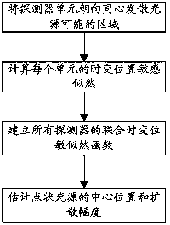
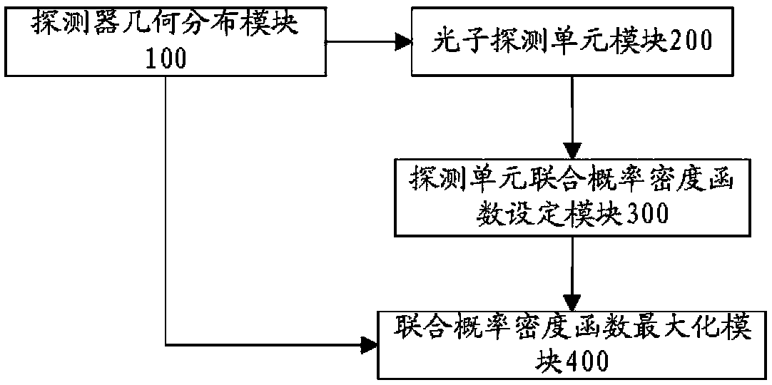
The invention discloses a concentric divergent light source detection method. The method comprises the following steps that a detector unit faces the area likely to be hit by a concentric divergent light source; by means of online or offline calculation, a time-varying position sensitivity likelihood probability function of each unit is obtained; within a given time interval, by means of first-principle computation and Monte-Carlo simulation, a joint time-varying position sensitivity likelihood function of all detectors is built; by maximizing the joint time-varying position sensitivity likelihood function of all the detectors, the central position and diffusion amplitude of a point-shaped light source are estimated, and a point-shaped light source parameter meeting maximization of the joint time-varying position sensitivity likelihood function of all the detectors serves as an estimated value of the point-shaped light source attribute. A concentric divergent light source detection device comprises a detector geometric distribution module, a photon detection unit module, a detection unit joint probability density function setting module and a joint probability density function maximization module. The method and device are specially suitable for in-vivo small animal imaging and superficial clinical diagnosis.

Description

technical field [0001] The invention relates to the technical fields of digital signal processing, photoelectric signal processing and nuclear detection, in particular to a detection method and device for a concentric divergent light source. Background technique [0002] A concentric divergent light source refers to a central divergent light source whose volume is less than or equal to 5cm or less than 5% of the total field of view area or volume. Since concentric divergent light sources are widely used in optical imaging, radiation imaging, and high-energy particle imaging, the detection method for concentric divergent light sources will become the most basic technological innovation in related fields, and will completely change its system architecture and data processing methods. The traditional concentric divergent light source detection uses various plane camera technologies and performs related 3D reconstruction (optical camera) on this basis; or measures the projection...

Claims


Application Information

Patent Timeline
IPC IPC(8): G01M11/02
CPCG01M11/0207
Inventor 邓贞宙
Owner NANCHANG UNIV
Why Eureka
Try Eureka