A mosaic detector geometric correction phantom and correction method

A technology of geometric correction and correction method, applied in the field of radiation imaging, can solve problems such as correction processing, and achieve the effect of ensuring accuracy

Active Publication Date: 2019-03-15
NANOVISION TECHNOLOGY (BEIJING) CO LTD
View PDF7 Cites 0 Cited by
  • Summary
  • Abstract
  • Description
  • Claims
  • Application Information

AI Technical Summary

Problems solved by technology

[0005] As for the image distortion caused by stitching gaps, there is currently no corresponding method for correction

Method used


Image

  • A mosaic detector geometric correction phantom and correction method
  • A mosaic detector geometric correction phantom and correction method
  • A mosaic detector geometric correction phantom and correction method

Examples


Embodiment Construction

[0047] The technical content of the present invention will be described in detail below in conjunction with the accompanying drawings and specific embodiments.

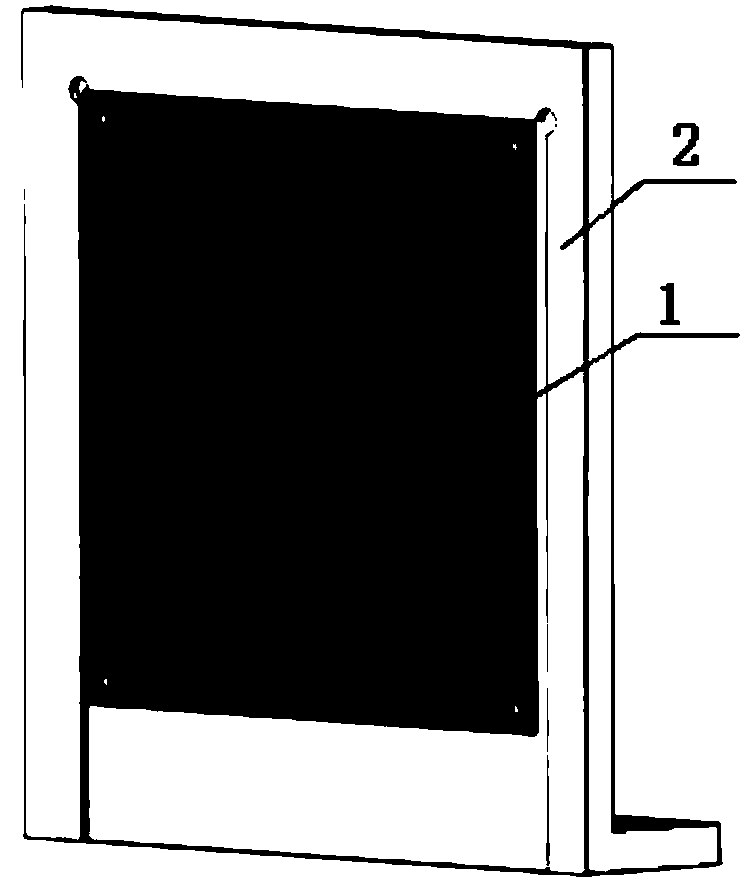
[0048] Such as figure 2 As shown, the spliced ​​detector geometric correction phantom provided by the present invention includes a geometric correction phantom substrate 1 and a geometric correction phantom mounting plate 2 . Wherein, the geometric correction phantom substrate 1 is a copper-clad laminate, which is a rectangular plate. Four openings are respectively provided at the four ends of the rectangular plate for installing the geometric correction phantom base plate 1 on the geometric correction phantom mounting plate 2 by means of screw connection. The geometric correction phantom substrate 1 is provided with a plurality of metal dots arranged at equal intervals. The metal dots can be made of metals such as tungsten, nickel, copper, etc. Currently, copper dots are usually used. For the convenience of descr...


PUM


Abstract

The invention discloses a splicing detector geometry correction body model and a correction method thereof. The method comprises the following steps of S1, installing a geometry correction body model on a splicing detector top surface so that metal round dots on a geometry correction body model substrate are uniformly distributed a photon counting chip; S2, taking the photon counting chip as an unit, dividing a photon counting detector top surface into a plurality of module groups, and according to positions of the metal round dots, calculating center coordinates of all the metal round dots in each module group; S3, calculating a pixel of each module group image, according to the pixel of each module group image, determining whether a seam exists between the adjacent module groups, if the seam exists, entering into a stepS4; otherwise, the seam does not exist, the image does not need to be corrected; and S4, calculating a pixel number of the seam existing between the adjacent module groups and restoring the pixel at the seam to the image. By using the method, actual image detected by the splicing detector can be effectively corrected and image accuracy is ensured.

Description

technical field [0001] The invention relates to a geometric correction phantom, in particular to a splicing detector geometric correction phantom, and at the same time relates to a correction method for splicing detector correction based on the geometric correction phantom, which belongs to the technical field of radiation imaging. Background technique [0002] In the field of radiation imaging, photon counting imaging technology is currently becoming a research hotspot in the industry due to the low dose of X-rays required. An existing photon-counting imaging detector is a photon-counting imaging device counted by a single X-ray, including: a layer of photosensitive material, a photosensitive material of a photodetector diode layer arranged in an N×M array, an N×M Array readout unit (the readout unit includes a high-gain, low-noise amplifying element, one readout unit is assigned to each photodetector diode); the readout unit is controlled by the data processing element, an...

Claims


Application Information

Patent Timeline
Patent Type & Authority Patents(China)
IPC IPC(8): G06T5/00G06T7/30
CPCG06T5/006G06T2207/10116G06T2207/20221
Inventor 康小维常彤崔志立
Owner NANOVISION TECHNOLOGY (BEIJING) CO LTD
Why Eureka
Try Eureka