Efficient dispersing machine capable of achieving stable grip

A disperser and high-efficiency technology, applied in mixers, mixer accessories, dissolving and other directions, can solve the problems of self-heavy material container, affect work efficiency, time-consuming and troublesome, etc., and achieve the effect of convenient dispersion of raw materials, prevention of contamination, and firm connection.

Inactive Publication Date: 2019-04-02
朱高鸣
View PDF0 Cites 0 Cited by
  • Summary
  • Abstract
  • Description
  • Claims
  • Application Information

AI Technical Summary

Problems solved by technology

Since the use of high-speed agitators (such as disc saw-tooth agitators) can form a strong turbulent flow locally, it usually has a strong dispersing and emulsifying effect on materials, so this type of high-speed agitator is also called a disperser. However, because The mixing range of the agitator is small. Although the stirring turbulence effect is strong on the plane where it is located, the dispersion of the material needs to ensure its uniformity, and the flow between the upper and lower layers of the material in the current disperser can only rely on the small vortex generated by the turbulence. In addition, the current dispersing machine has different fixing methods for the filling cylinder according to the different volumes. For large-scale dispersing machines, due to the heavy weight of the filling cylinder, it is generally not equipped with a fixing device and relies on the filling material The self-weight of the barrel ensures that it will not shake due to the stirring force, but for smaller mixers, the position of the middle clamp is usually adjusted by manually turning the bolts to fix it, which is time-consuming and troublesome, and it is inconvenient to move, which brings a lot of inconvenience to people

Method used


Image

  • Efficient dispersing machine capable of achieving stable grip
  • Efficient dispersing machine capable of achieving stable grip
  • Efficient dispersing machine capable of achieving stable grip

Examples


Embodiment Construction

[0023] The following will clearly and completely describe the technical solutions in the embodiments of the present invention with reference to the accompanying drawings in the embodiments of the present invention. Obviously, the described embodiments are only some, not all, embodiments of the present invention. Based on the embodiments of the present invention, all other embodiments obtained by persons of ordinary skill in the art without making creative efforts belong to the protection scope of the present invention.

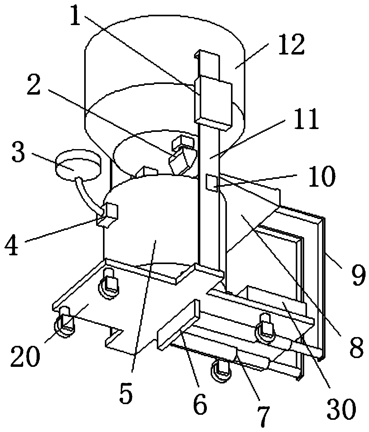
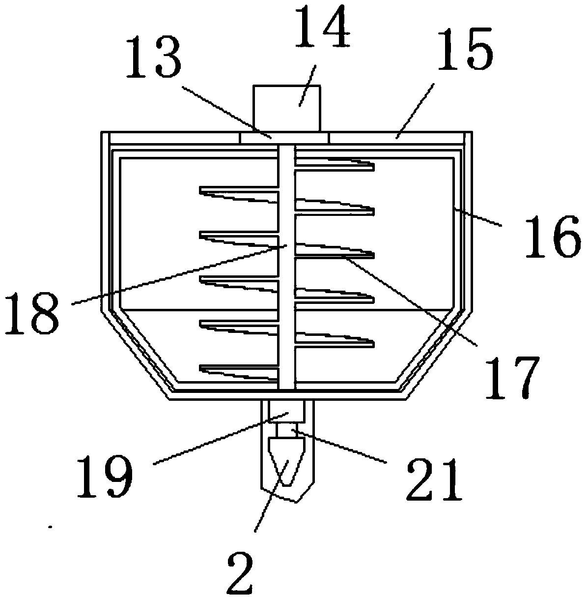
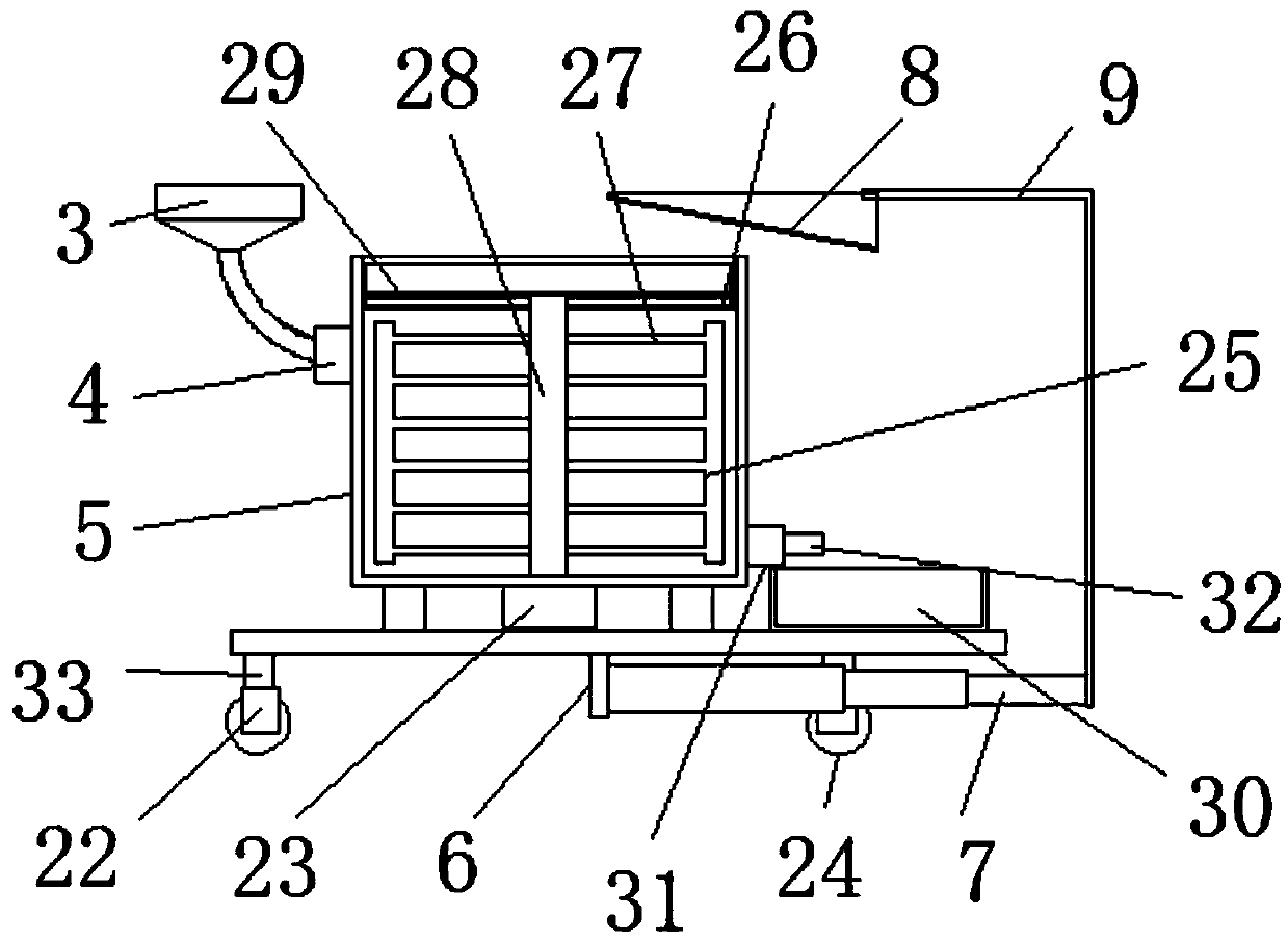
[0024] see Figure 1-3, the present invention provides a technical solution: a high-efficiency dispersing machine with stable grip, including a support base plate 20, the upper surface of the support base plate 20 is connected with a liquid dispersion shell 5 through four support columns, and the upper end of one side of the liquid dispersion shell 5 A feed inlet is provided, and a liquid inlet conduit is welded on one side of the feed inlet of the liquid disp...


PUM


Abstract

The invention discloses an efficient dispersing machine capable of achieving stable grip, comprising a supporting bottom plate, the upper surface of the supporting bottom plate is connected with a liquid dispersing outer casing through four supporting columns, the upper end of one side of the liquid dispersing outer casing is provided with a feeding port, and one side of the feeding port of the liquid dispersing outer casing is welded with a liquid inlet pipe; one end, away from connection with the liquid dispersing outer casing, of the liquid inlet pipe is provided with a feeding head; and the four supporting columns are evenly distributed around the center of the liquid dispersing outer casing, the center of the lower surface of the liquid dispersing outer casing is connected with a second dispersing motor by bolts, and the output shaft of the second dispersing motor penetrates and extends to the inner bottom surface of the liquid dispersing outer casing. The efficient dispersing machine capable of achieving stable grip has a simple structure and simple operation, the machine can be more conveniently moved, also solid raw materials can be dispersed, a liquid can be dispersed, thus the dispersion is more convenient, and the dispersing machine is stable in grip.

Description

technical field [0001] The invention relates to the technical field of dispersing machines, in particular to a high-efficiency dispersing machine with stable grip. Background technique [0002] A disperser is a type of mixer in a broad sense. Since the use of high-speed agitators (such as disc saw-tooth agitators) can form a strong turbulent flow locally, it usually has a strong dispersing and emulsifying effect on materials, so this type of high-speed agitator is also called a disperser. However, because The mixing range of the agitator is small. Although the stirring turbulence effect is strong on the plane where it is located, the dispersion of the material needs to ensure its uniformity, and the flow between the upper and lower layers of the material in the current disperser can only rely on the small vortex generated by the turbulence. In addition, the current dispersing machine has different fixing methods for the filling cylinder according to the different volumes. F...

Claims


Application Information

Patent Timeline
Patent Type & Authority Applications(China)
IPC IPC(8): B01F13/10B01F15/00B01F15/02B01F13/00
CPCB01F33/501B01F33/821B01F35/211B01F35/123B01F35/2111B01F35/754
Inventor 朱高鸣叶诚帆赖传柏
Owner 朱高鸣
Why Eureka
Try Eureka