Machining drilling device with protective function

A drilling device and machining technology, applied in the direction of positioning device, boring/drilling, metal processing equipment, etc., can solve the problems of not being blocked by waste chips, operator injury, waste chips splashing, etc., to achieve convenient rotation and operation Convenience and time-saving effects

Active Publication Date: 2019-04-02
盐城市景睿模具科技有限公司
View PDF11 Cites 9 Cited by
  • Summary
  • Abstract
  • Description
  • Claims
  • Application Information

AI Technical Summary

Problems solved by technology

[0004] The purpose of the present invention is to provide a kind of drilling device with protective function for mechanical processing, to solve the problem that the drilling device for mechanical processing on the market proposed by the above-mentioned background technology, in the process of processing, it is easy to cause the splash of waste chips, It is easy to cause injury to the operator, can not block the waste well, and when drilling holes on the opposite side plate, when it is necessary to drill holes on the back side of the opposite side plate, the square plate needs to be disassembled, and then the opposite side plate should be turned over again. The operation process is complicated, it is inconvenient to rotate the opposite plate, and it is inconvenient to drill holes on the back of the opposite plate

Method used


Image

  • Machining drilling device with protective function
  • Machining drilling device with protective function
  • Machining drilling device with protective function

Examples


Embodiment Construction

[0028] The following will clearly and completely describe the technical solutions in the embodiments of the present invention with reference to the accompanying drawings in the embodiments of the present invention. Obviously, the described embodiments are only some, not all, embodiments of the present invention. Based on the embodiments of the present invention, all other embodiments obtained by persons of ordinary skill in the art without making creative efforts belong to the protection scope of the present invention.

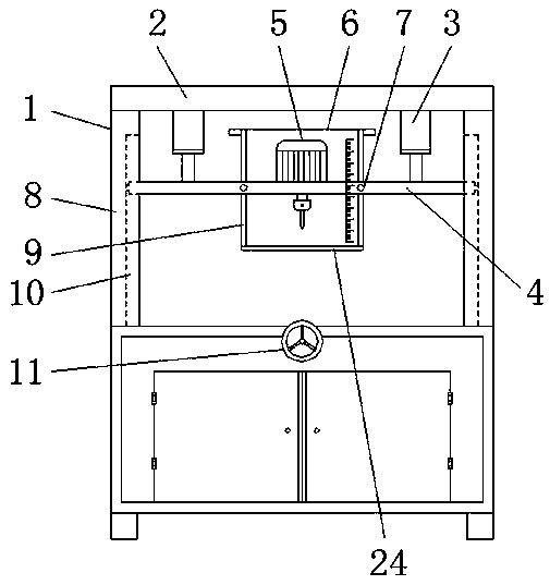
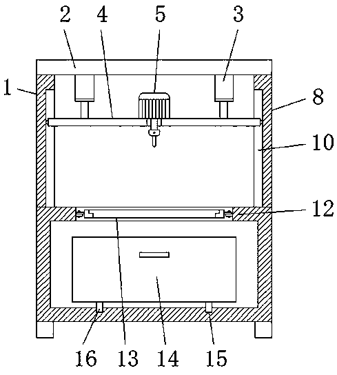
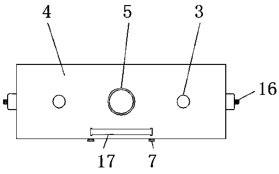
[0029] see Figure 1-8 , the present invention provides a technical solution: a drilling device for mechanical processing with a protective function, including a drilling device main body 1, a support frame 2, a hydraulic cylinder 3, a lifting plate 4, a motor 5, a protective plate 6, a tightening Nut 7, support rod 8, slide rail 9, lifting groove 10, hand wheel 11, processing table 12, fixed plate 13, chip bucket 14, sliding groove 15, moving wheel 16, slidin...


PUM


Abstract

The invention discloses a machining drilling device with a protective function. The machining drilling device comprises a drilling device body, a supporting frame, a hydraulic cylinder, a motor, a tightening nut, a supporting rod, a handwheel, a machining table, a chip collecting bucket and a moving wheel; and the supporting frame is arranged at the top of the drilling device body, the lower end of the supporting frame is connected with a lifting plate through the hydraulic cylinder, an anti-collision bar is arranged at the lower end of a protective plate, the supporting rod is welded to the lower end of the supporting frame, the machining table is arranged below the lifting plate, a moving groove is formed in the inner side of a fixing plate and is in bolt connection with a fixing bar, the chip collecting bucket is arranged under the fixing plate, the handwheel is arranged at the outer end of a rotating rod, the rotating rod is in bearing connection with the machining table, and a limiting block is arranged on the rear side inside the machining table. According to the machining drilling device with the protective function, waste chips generated during drilling can be isolated froman operator, and the operator conveniently rotates the fixing plate.

Description

technical field [0001] The invention relates to the technical field of machining, in particular to a drilling device for machining with protection function. Background technique [0002] Drilling device is a kind of processing device that carries out drilling to object, and for example the publication number is CN107824829A a kind of punching machine for mechanical processing, this punching machine for mechanical processing, through being set up at the joint of movable seat and slide bar and The round hole matched with the slide rod, and the inner wall of the round hole is set as a smooth surface, so as to effectively reduce the friction between the movable seat and the slide rod, and facilitate the stable movement of the movable seat along the surface of the slide rod. However, in the process of processing, It is easy to cause waste chips to splash, easy to cause injury to the operator, and can not block the waste chips well. Another example is a drilling device with a publ...

Claims


Application Information

Patent Timeline
Patent Type & Authority Applications(China)
IPC IPC(8): B23B41/00B23B47/00B23Q3/06B23Q11/08
CPCB23B41/00B23B47/00B23Q3/06B23Q11/08
Inventor 江前达
Owner 盐城市景睿模具科技有限公司
Why Eureka
Try Eureka