
Longitudinal cutting mechanism

A longitudinal cutting and main cutting technology, applied in other manufacturing equipment/tools, manufacturing tools, etc., can solve the problems of poor reliability, low cutting precision, and inability to realize rapid and continuous cutting, so as to improve work efficiency, fast slotting and cutting effect

Inactive Publication Date: 2019-04-02
吴安明
View PDF0 Cites 0 Cited by
  • Summary
  • Abstract
  • Description
  • Claims
  • Application Information

AI Technical Summary

Problems solved by technology

[0002] With the development of the modern mechanical processing industry, the requirements for cutting quality and precision are constantly improving, and the requirements for improving production efficiency, reducing production costs, and highly intelligent automatic cutting functions are also increasing; the development of CNC cutting machines must be Adapt to the requirements of the development of modern mechanical processing industry; cutting machines are divided into flame cutting machines, plasma cutting machines, laser cutting machines, water cutting, etc.; laser cutting machines have the fastest efficiency, highest cutting precision, and generally small cutting thickness; plasma cutting machines The cutting speed is also very fast, and the cutting surface has a certain slope; the flame cutting machine is aimed at thicker carbon steel materials; however, ordinary CNC cutting machines are generally used for wood processing, and the traditional cutting accuracy is low and the reliability is poor. , can not achieve rapid continuous cutting

Method used


Image

  • Longitudinal cutting mechanism

Examples


Embodiment Construction

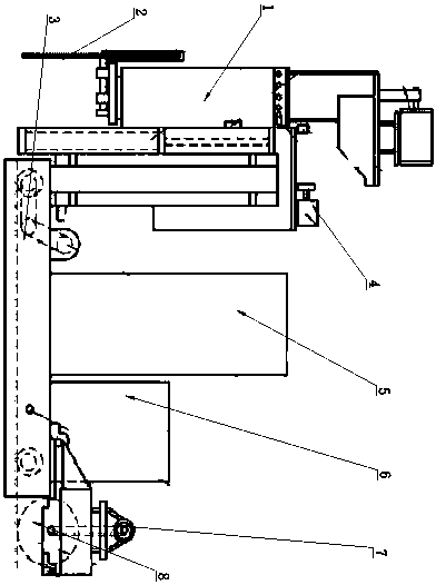
[0013] Such as figure 1 As shown, the purpose of the present invention is achieved in this way: a longitudinal cutting mechanism, including a base 3, the base 3 is arranged horizontally, an electric control cabinet 5 is arranged on the base 3, and the electric control cabinet 5 One side of the base 3 is provided with a hydraulic station 6, the far right side of the base 3 is provided with a slotting machine 8, the slotting machine 8 is driven by the driving device 7, and the slotting machine 8 is equipped with a lifting hydraulic cylinder, so The lifting hydraulic cylinder is directly fixed on the base 3; the left side of the base 3 is provided with a main cutting saw 2, and the main cutting saw 2 is longitudinally connected with a main saw lifting hydraulic cylinder 1, and the upper part of the main saw is matched with a There is a rotary motor 4, the bottom of the rotary motor 4 is directly connected with the main cutting saw 2, the base 3 is also equipped with a locking hyd...


PUM


Abstract

The invention relates to a longitudinal cutting mechanism in the field of cutting machines. The longitudinal cutting mechanism comprises a base, wherein the base is transversely arranged, an electriccontrol cabinet is arranged on the base, a hydraulic station is arranged on one side of the electric control cabinet, a grooving machine is arranged on the rightmost side of the base, the grooving machine is driven by a driving device, the grooving machine is provided with a lifting hydraulic cylinder in a matched mode, and the lifting hydraulic cylinder is directly fixed on the base; a main cutting saw is arranged on the left side of the base, a main saw lifting hydraulic cylinder is longitudinally connected to the main cutting saw, a rotary motor is arranged above the main saw in a matched mode, the lower portion of the rotary motor is directly connected with the main cutting saw, the base is further provided with a locking hydraulic cylinder in a matched mode, the locking hydraulic cylinder is fixed on the main saw lifting hydraulic cylinder, a cart hydraulic motor is further arranged on the base, a trolley hydraulic motor is arranged on the cart hydraulic motor in a matched mode, and a trolley brake hydraulic cylinder is arranged on the trolley hydraulic motor in a matched mode. The longitudinal cutting mechanism can rapidly carry out grooving and cutting on materials, and improves the working efficiency.

Description

technical field [0001] The invention relates to a longitudinal cutting mechanism in the field of cutting machines. Background technique [0002] With the development of the modern mechanical processing industry, the requirements for cutting quality and precision are constantly improving, and the requirements for improving production efficiency, reducing production costs, and highly intelligent automatic cutting functions are also increasing; the development of CNC cutting machines must be Adapt to the requirements of the development of modern mechanical processing industry; cutting machines are divided into flame cutting machines, plasma cutting machines, laser cutting machines, water cutting, etc.; laser cutting machines have the fastest efficiency, highest cutting precision, and generally small cutting thickness; plasma cutting machines The cutting speed is also very fast, and the cutting surface has a certain slope; the flame cutting machine is aimed at thicker carbon ste...

Claims


Application Information

Patent Timeline
Patent Type & Authority Applications(China)
IPC IPC(8): B23P23/02B23D79/00
CPCB23P23/02B23D79/00
Inventor 吴安明
Owner 吴安明
Learn More