
A method for preparing a polyurethane-supported sticking corner of a megawatt wind turbine blade

A wind turbine and polyurethane technology, which is applied to household appliances, other household appliances, household components, etc., can solve the problems of difficulty in ensuring the conformability of the sticking angle, difficulty in guaranteeing the bonding gap, and risk of blade bonding, and achieve production costs. Low, wrinkle reduction, strong follow-up effect

Active Publication Date: 2021-05-04
SINOMATECH WIND POWER BLADE
View PDF2 Cites 0 Cited by
  • Summary
  • Abstract
  • Description
  • Claims
  • Application Information

AI Technical Summary

Problems solved by technology

[0002] At present, in the blade production process, the paste angle is the main component of the wind turbine composite material wind turbine blade. The paste angle structure is directly connected with the glass fiber reinforced plastic on one side of the shell by hand laying, and connected with the other shell through the adhesive. , the shape of the bonding surface of the pasting angle is mainly determined by the shape of the bonding inner cavity of the shell. At present, the size of wind turbine blades is getting larger and the shape is becoming more and more complicated. The shape is random, and under the influence of the operation process, it is difficult to guarantee the bonding gap, and it is easy to cause defects such as rich resin at the corners of the paste, wrinkles at the paste corners, etc., which brings great risks to the blade bonding

Method used


Image

  • A method for preparing a polyurethane-supported sticking corner of a megawatt wind turbine blade
  • A method for preparing a polyurethane-supported sticking corner of a megawatt wind turbine blade
  • A method for preparing a polyurethane-supported sticking corner of a megawatt wind turbine blade

Examples


Embodiment 1

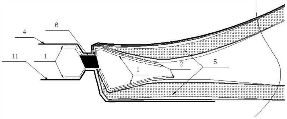
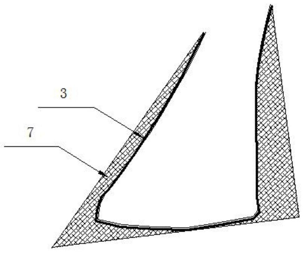
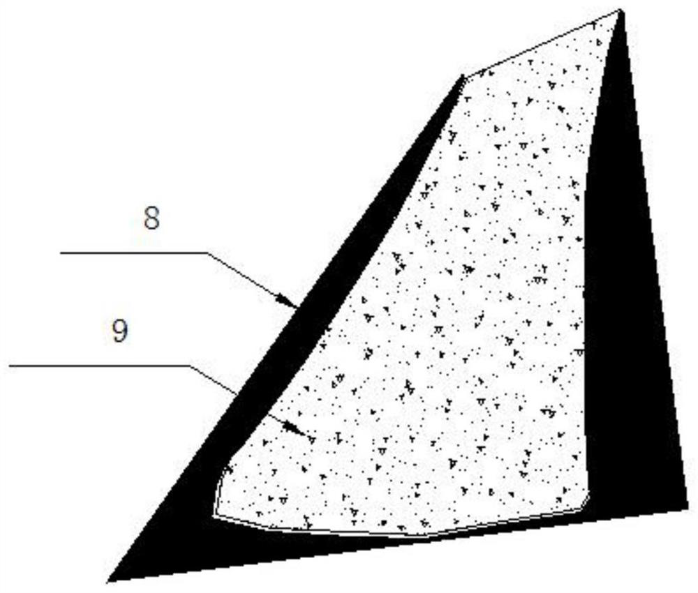
[0027] Such as figure 1 , figure 2 , image 3 and Figure 4 As shown, taking the preparation method of the adhesive angle with polyurethane support for the blade of a megawatt-class wind power generator, taking the trailing edge adhesive angle of a 64.2m wind turbine blade as an example, it includes the following steps:

[0028] Firstly, in the 64.2m mold with blade curing shell, the inner cavity 3 of the polyurethane foam female mold corresponding to the design position of the pasting angle of the rear edge is reproduced;

[0029] a. Lay the release cloth 1 on the pressure surface mold 4 and the suction surface mold 11 at the design position of the 64.2m trailing edge paste angle with the solidified shell 5, and then lay the fiber cloth 2 on the release cloth 1 respectively , and then cover the release cloth 1 on the surface of the fiber cloth 2 respectively, and form the inner cavity 3 of the polyurethane foam female mold after curing, tear off the part of the release cl...


PUM

PropertyMeasurementUnit
thicknessaaaaaaaaaa
thicknessaaaaaaaaaa

Abstract

The invention discloses a method for preparing a blade of a megawatt-level wind power generator with a polyurethane support sticking angle, the method comprising making the inner cavity (3) of a polyurethane foaming female mold, and manufacturing the inner cavity (3) of the polyurethane foaming female mold Polyurethane foaming female mold (8), then make polyurethane support (9) according to polyurethane foaming female mold (8), according to the layering sequence of pasting corner (10), lay the fiber cloth of pasting corner, at pasting corner (10) The polyurethane support (9) is placed in the cavity area, and a vacuum system is laid. After the hand lay-up is laid, vacuum is applied to obtain the pasting corner. The invention has reasonable process design and strong operability, can effectively ensure the conformity between the blade pasting angle and the shell cavity, is beneficial to ensure the gap between the blade pasting angle and the blade shell, and greatly reduces the pasting caused by the manufacture of the blade pasting angle There are defects such as corner wrinkles, large bonding gaps, and resin-rich corners of the pasting corners. The prepared pasting corners have strong conformability, strong practicability, and low production costs.

Description

technical field [0001] The patent of the present invention relates to a preparation method of a wind turbine blade component of a wind power generator set, in particular to a preparation method of a polyurethane-supported pasting corner of a megawatt wind power generator blade. Background technique [0002] In the current blade production process, the paste angle is the main component of the wind turbine composite material wind turbine blade. The paste angle structure is directly connected with the glass fiber reinforced plastic on one side of the shell by hand lay-up, and connected with the other shell through an adhesive. , the shape of the bonding surface of the pasting angle is mainly determined by the shape of the bonding inner cavity of the shell. At present, the size of wind turbine blades is getting larger and the shape is becoming more and more complicated. The shape is random, and under the influence of the operation process, it is difficult to guarantee the bondin...

Claims


Application Information

Patent Timeline
Patent Type & Authority Patents(China)
IPC IPC(8): B29C70/68B29C33/38B29L31/08
CPCB29C33/3842B29C70/68B29C70/681B29C70/682B29C70/683B29L2031/085
Inventor 刘卫生乔小亮吕召涛常江徐庆伟武赛娟
Owner SINOMATECH WIND POWER BLADE
Learn More