
Cantilever scaffold

A technology of cantilevered scaffolding and scaffolding, which is applied in the field of cantilevered scaffolding, can solve the problems of increasing construction cost, delaying construction progress, and serious leakage hidden dangers, and achieves the effects of preventing grout leakage, improving construction quality, and simple operation

Pending Publication Date: 2019-04-02
NO 2 CONSTR GRP CO LTD OF SHANGHAI CONSTR GRP
View PDF0 Cites 11 Cited by
  • Summary
  • Abstract
  • Description
  • Claims
  • Application Information

AI Technical Summary

Problems solved by technology

[0002] At present, the traditional cantilevered scaffolding on the construction site is fixed on the floor slab with I-beam through the wall. Due to the popularization and application of aluminum formwork, opening holes in the aluminum formwork will not only increase the construction cost and delay the construction progress, but will also cause A large amount of manpower and material resources are wasted during concrete pouring and subsequent repairs, and there are serious leakage hazards.

Method used


Image

  • Cantilever scaffold
  • Cantilever scaffold
  • Cantilever scaffold

Examples


Embodiment 1

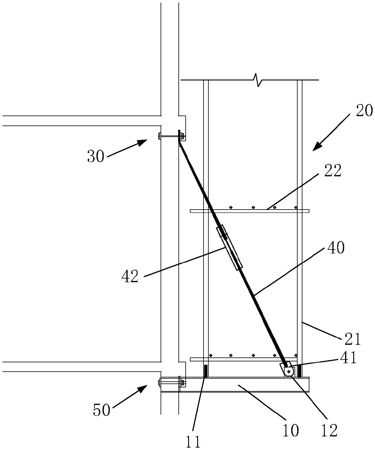
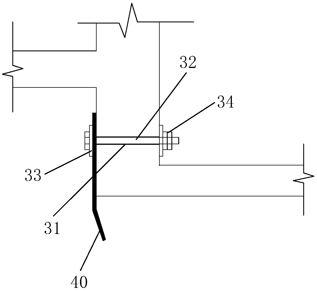
[0026] For the cantilevered scaffold provided by the present invention, please refer to Figure 1 to Figure 3 , comprising a cantilevered steel 10 (No. 18 I-beam), a scaffold body 20, a first tie anchor 30 and a steel wire rope 40, the cantilevered steel 10 is fixed on the substructure floor and extends outward in the horizontal direction, The scaffold body 20 is fixedly installed on the extension section of the cantilevered steel 10, the first tie anchor 30 is fixed in the reinforced concrete structure, and the two ends of the steel wire rope 40 are connected with the first tie respectively. The anchorage 30 is fixedly connected with the cantilever steel 10 . The present invention uses the first tie anchor 30 and the cantilevered steel 10 to connect the two ends of the steel wire rope 40 to realize a pull-up cantilevered scaffold, which can effectively prevent the mold explosion phenomenon of the connection part of the outer wall panel during concrete pouring, and The operat...

Embodiment 2

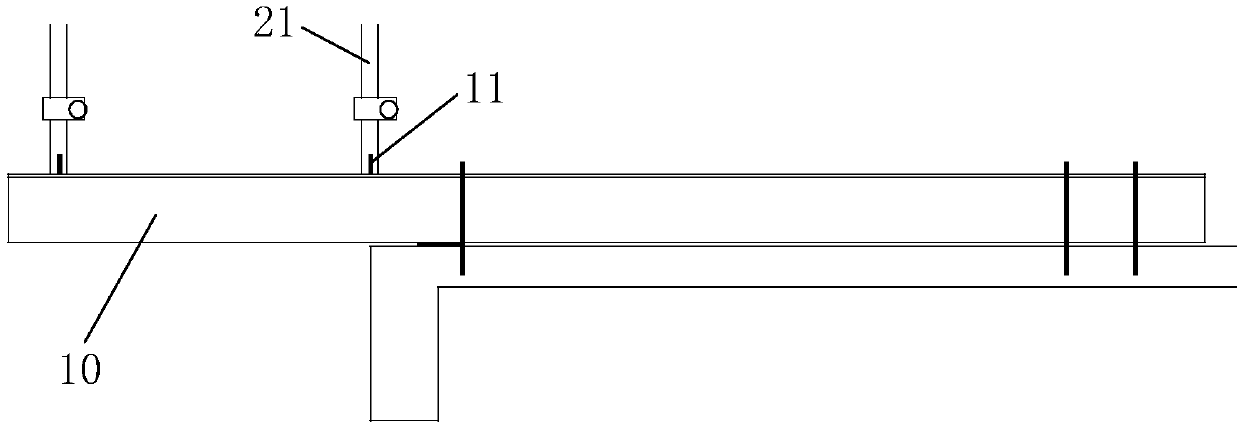
[0033] Please focus on reference Figure 4 The difference between this embodiment and Embodiment 1 is that the number of the steel wire ropes 40 is two, and one end of the two steel wire ropes 40 is fixed on the first tie anchor 30, and the other ends are respectively fixed on the On the fixing bases 12 corresponding to the two steel bar heads 11 respectively, in other words, in the present invention, two tie knots are arranged at the position where the tie strength needs to be increased (such as the window position).

[0034] Preferably, please continue to refer to Figure 4 , the angle between the steel wire rope 40 on the inside and the vertical surface is 19°~35°; the angle between the steel wire rope 40 on the outside and the vertical surface is 19°~45°. The angle between the steel wire rope 40 and the vertical plane is greater than the angle between the inside steel wire rope 40 and the vertical plane.

[0035] In summary, the cantilevered scaffold provided by the pres...


PUM

PropertyMeasurementUnit
Horizontal spacingaaaaaaaaaa

Abstract

The invention relates to a cantilever scaffold, which comprises cantilever profile steel, a scaffold body, a first tie anchorage device and a steel wire rope. The cantilever profile steel is fixed toa bottom layer structure floor and outwards extends in the horizontal direction; the scaffold body is fixedly mounted on the extending section of the cantilever profile steel, and the first tie anchorage device is fixed into a reinforced concrete structure; and the two ends of the steel wire rope are fixedly connected with the first tie anchorage device and the cantilever profile steel correspondingly. The first tie anchorage device and the cantilever profile steel are utilized to be connected with the two ends of the steel wire rope to achieve the upward-pulling-type cantilever scaffold, andthe outer wallboard connecting parts can be effectively prevented from generating a formwork blasting phenomenon during concrete pouring; and operation is easy, construction is convenient and rapid, the construction quality can be effectively improved, and the later-period repairing cost is reduced.

Description

technical field [0001] The invention relates to the field of building construction, in particular to a cantilevered scaffold. Background technique [0002] At present, the traditional cantilevered scaffolding on the construction site is fixed on the floor slab with I-beam through the wall. Due to the popularization and application of aluminum formwork, opening holes in the aluminum formwork will not only increase the construction cost and delay the construction progress, but will also cause A lot of manpower and material resources are wasted during concrete pouring and late repairs, and there are serious leakage hidden dangers. [0003] Therefore, how to provide a cantilevered scaffold that is suitable for aluminum molds, has low construction cost, and can reduce the hidden danger of leakage is a technical problem to be solved urgently by those skilled in the art. Contents of the invention [0004] The invention provides a cantilevered scaffold to solve the above technica...

Claims


Application Information

Patent Timeline
IPC IPC(8): E04G3/18E04G5/04
CPCE04G3/18E04G5/04E04G5/046
Inventor 马跃强徐铭泽陆冬兴成炜张永徐飞飞董建国
Owner NO 2 CONSTR GRP CO LTD OF SHANGHAI CONSTR GRP
Learn More