Buffer base for die casting machine

A technology of die-casting machine and buffer device, which is applied in the direction of supporting machines, mechanical equipment, machine tables/supports, etc., can solve the problems that the die-casting machine base cannot be raised and lowered, the service life of the die-casting machine is affected, and the buffering effect of the base is not obvious. Pressure, easy operation, the effect of increasing stability

Inactive Publication Date: 2019-04-02
BENGBU LONGHUA DIE CASTING MACHINE CO LTD
View PDF6 Cites 4 Cited by
  • Summary
  • Abstract
  • Description
  • Claims
  • Application Information

AI Technical Summary

Problems solved by technology

The die-casting machine hydraulically injects molten metal into the mold for cooling and forming under pressure, and solid metal castings can be obtained after the mold is opened. The user of the die-casting machine needs to have a good buffer effect to ensure its normal die-casting work, while the existing The cush

Method used


Image

  • Buffer base for die casting machine
  • Buffer base for die casting machine

Examples


Embodiment 1

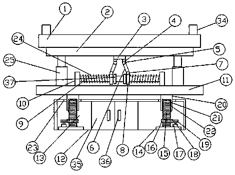
[0027] see figure 1 , a buffer base for a die-casting machine according to an embodiment of the present invention, comprising a top plate 1, a support plate 2 is fixed under the top plate 1, a fixed plate 3 is fixed under the support plate 2, and the fixed plate 3 Connecting blocks 4 are fixed at both ends, and a first rotating shaft 5 is arranged on the connecting block 4, and a connecting rod 6 is connected to the first rotating shaft 5, and a second rotating shaft 7 is provided on the other end of the connecting rod 6. , the second rotating shaft 7 is movably connected with a slider 8, the slider 8 is provided with a sliding rod 9, the connecting ends of the sliding rod 9 are provided with first springs 24, and the two ends of the sliding rod 9 All are provided with connecting plate 10, described connecting plate 10 below is provided with base plate 11, and described connecting plate 10 is fixed on described base plate 11, and described base plate 11 below is provided with ...

Embodiment 2

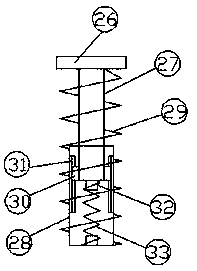
[0030] Such as Figure 1-2As shown, both ends of the top plate 1 are provided with limiting plates 34; both ends of the top plate 1 are provided with limiting plates 34, which can help the die-casting machine to be fixed on the top plate 1 and increase its stability. A buffer device 25 is symmetrically provided between the support plate 2 and the base plate 11; a buffer device 25 is symmetrically provided between the support plate 2 and the base plate 11, which can help the first spring 24 to play a buffering role. , reducing the pressure on the first spring 24 can effectively support the die-casting machine. The buffer device 25 includes a horizontal plate 26, a second support rod 27 is arranged below the horizontal plate 26, and a third support rod 28 is provided outside the second support rod 27, and the second support rod 27 and the The third support rod 28 is covered with a second spring 29, and one end of the second support rod 27 located in the third support rod 28 is ...


PUM


Abstract

The invention discloses a buffer base for a die casting machine. The buffer base for the die casting machine comprises a roof. Connecting blocks are fixed to both ends of a fixed plate, first rotatingshafts are arranged on the connecting blocks, and second rotating shafts are arranged at the other ends of connecting rods. Through the action of sliding blocks and first springs, the buffer functioncan be achieved to ensure the normal operation of the die casting machine. Lifting devices are symmetrically arranged in lifting boxes, the lifting devices comprise supporting blocks, thread rods arearranged on the supporting blocks, first gears are arranged on the thread rods, driving motors are arranged on one sides of the supporting blocks, and second gears are driven to rotate by the drivingmotors. The second gears drive the first gears to rotate, the first gears drive the thread rods to rotate, and through the coordination between the thread rods and inner threads in first supporting rods, a bottom plate can be lifted and dropped. The buffer base for the die casting machine has the beneficial effects that the structure of the device is simple, the operation is convenient, and the supporting action can be effectively played to the die casting machine; and meanwhile, the buffer action can be effectively played to the die casting machine, and the height can be adjusted.

Description

technical field [0001] The invention relates to the technical field of die-casting machine auxiliary equipment, in particular to a buffer base for a die-casting machine. Background technique [0002] A die casting machine is a machine used for pressure casting. Including hot press chamber and cold press chamber. Finally, they are divided into two types: straight and horizontal. The die-casting machine hydraulically injects the molten metal into the mold for cooling and forming under pressure. After the mold is opened, a solid metal casting can be obtained. The user of the die-casting machine needs to have a good buffer effect to ensure its normal die-casting work, while the existing The cushioning effect of most bases of die-casting machines is not obvious, and die-casting machines are generally placed directly on the ground, long-term placement will cause corrosion at the bottom, affecting the service life of die-casting machines, and the existing bases of die-casting m...

Claims


Application Information

Patent Timeline
IPC IPC(8): F16M11/04F16M11/18F16M11/24F16F15/04
CPCF16F15/04F16M11/04F16M11/18F16M11/24
Inventor 周文平
Owner BENGBU LONGHUA DIE CASTING MACHINE CO LTD
Why Eureka
Try Eureka