
Temperature adjusting device and water heater

A technology of temperature adjustment device and heat exchanger, which is applied in the directions of fluid heater, lighting and heating equipment, etc., can solve the problems of leakage of refrigerant or heat storage material, low heat exchange efficiency of heat storage part, etc.

Pending Publication Date: 2019-04-02
GREE ELECTRIC APPLIANCES INC
View PDF6 Cites 2 Cited by
  • Summary
  • Abstract
  • Description
  • Claims
  • Application Information

AI Technical Summary

Problems solved by technology

[0006] The present invention aims to provide a temperature regulating device and a water heater to improve the problems existing in the prior art that the heat exchange efficiency of the heat storage part is low, and the leakage of refrigerant or heat storage material leads to the safety of water

Method used


Image

  • Temperature adjusting device and water heater
  • Temperature adjusting device and water heater

Examples


Embodiment 1

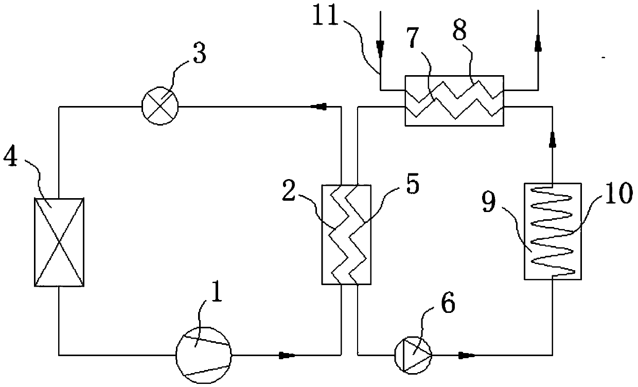
[0038] figure 1 A schematic diagram of the principle of the temperature regulating device of this embodiment is shown. Such as figure 1 As shown, the temperature regulating device of this embodiment includes a refrigerant circuit, and the refrigerant circuit includes a compressor 1 , a condenser 2 , a throttling component 3 and an evaporator 4 connected in sequence.

[0039] The refrigerant compressed by the compressor 1 condenses and releases heat in the condenser 2. The condensed refrigerant enters the evaporator 4 after being throttled and reduced by the throttling part 3. The refrigerant evaporates and absorbs heat in the evaporator 4 and then is compressed. The suction port of the machine 1 returns to the compressor 1 to be compressed again.

[0040] The temperature regulating device also includes a medium circuit, and the medium circuit includes a first heat exchanger 5 that exchanges heat with the condenser 2, an accumulator 9 that communicates with the outlet of the ...

Embodiment 2

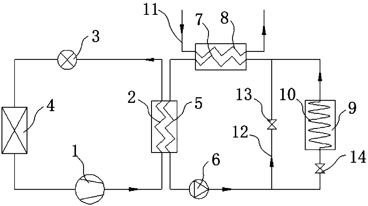
[0068] figure 2 A schematic diagram of the principle of the temperature regulating device of this embodiment is shown. Such as figure 2 As shown, the difference between this embodiment and Implementation 1 lies in:

[0069] The medium circuit comprises a first branch 12 and a second branch, wherein the energy store 9 is arranged in the second branch. The inlets of the first and second branches are both connected to the outlet of the first heat exchanger 5 , and the outlets of the first and second branches are both connected to the inlet of the second heat exchanger 7 .

[0070] The medium circuit also includes an inlet for controlling the communication of the second heat exchanger 7 with the first branch 12 and / or the accumulator 9 .

[0071] The control valve comprises a first valve 13 arranged in the first branch 12 and a second valve arranged in the second branch.

[0072] To sum up, the inlet of the second heat exchanger 7 in this embodiment can be selectively commun...


PUM


Abstract

The invention relates to a temperature adjusting device and a water heater. The temperature adjusting device comprises a refrigerant loop, a medium loop and a third heater exchanger (8); the refrigerant loop comprises a compressor (1), a condenser (2) and an evaporator (4); the medium loop comprises a first heat exchanger (5) used for exchanging heat with the condenser (2) or the evaporator (4), an energy accumulator (9) communicating with an outlet of the first heat exchanger (5) and a second heat exchanger (7) communicating with an outlet of the energy accumulator (9); and the third heater exchanger (8) is configured to be capable of exchanging heat with the second heat exchanger (7) and used for allowing a fluid needing to be heated or cooled to circulate. By applying the technical scheme, the heat absorbing process and the heat releasing process of the energy accumulator both can be completed in the mode of exchanging heat with a medium in the medium loop, and therefore the problemthat in the prior art, heater exchangers in a heat accumulator can not fully exchange heat with a heat accumulation portion, and the water use safety problem caused by refrigerating agent leaking andheat accumulation material corrosion leaking are solved.

Description

technical field [0001] The invention relates to the field of refrigerant circulation equipment, in particular to a temperature regulating device and a water heater. Background technique [0002] Air source heat pump water heaters have been widely promoted and applied due to their energy saving, environmental protection, and safety features. Restricted its further popularization and use. [0003] Phase change energy storage technology uses phase change materials to absorb and release heat during the state change process to achieve the purpose of energy supply and demand transfer in time and space. [0004] Applying phase change energy storage technology to air source heat pump water heaters can use the latent heat of phase change materials to store and release heat. Due to the high heat storage density of heat storage materials and the relatively stable phase change temperature, phase change heat storage water heaters have energy storage capabilities. It has the advantages ...

Claims


Application Information

Patent Timeline
IPC IPC(8): F24H4/02F24H9/00
CPCF24H4/02F24H9/0005
Inventor 方金升梁祥飞徐箐马菀陈昊
Owner GREE ELECTRIC APPLIANCES INC
Learn More