
Display panel and manufacturing method thereof, and display device

A display panel and display device technology, applied in nonlinear optics, instruments, optics, etc., can solve problems such as optical signal and sound signal loss, and achieve the effect of improving performance

Active Publication Date: 2019-04-02
XIAMEN TIANMA MICRO ELECTRONICS
View PDF7 Cites 13 Cited by
  • Summary
  • Abstract
  • Description
  • Claims
  • Application Information

AI Technical Summary

Problems solved by technology

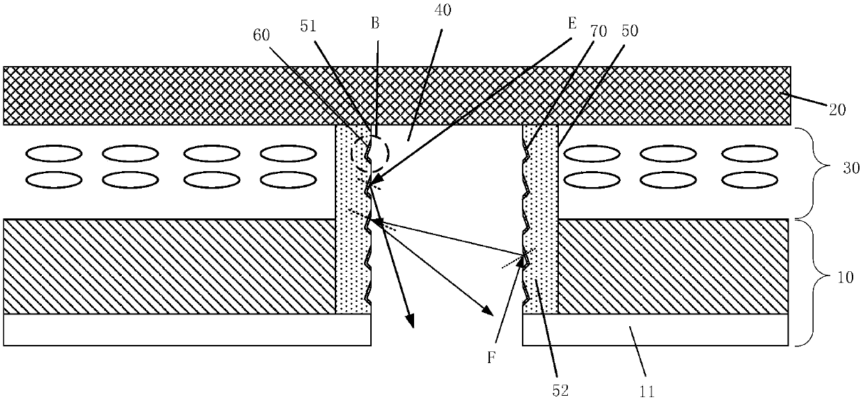
The optical signal and the sound signal are transmitted from the through hole to the camera and other devices. Due to the multiple reflection and refraction of the optical signal and the sound signal in the through hole, the optical signal and the sound signal will have a large loss

Method used


Image

  • Display panel and manufacturing method thereof, and display device
  • Display panel and manufacturing method thereof, and display device
  • Display panel and manufacturing method thereof, and display device

Examples


Embodiment Construction

[0027] Various exemplary embodiments of the present invention will now be described in detail with reference to the accompanying drawings. It should be noted that the relative arrangements of components and steps, numerical expressions and numerical values ​​set forth in these embodiments do not limit the scope of the present invention unless specifically stated otherwise.

[0028] The following description of at least one exemplary embodiment is merely illustrative in nature and in no way taken as limiting the invention, its application or uses.

[0029] Techniques, methods and devices known to those of ordinary skill in the relevant art may not be discussed in detail, but where appropriate, such techniques, methods and devices should be considered part of the description.

[0030] In all examples shown and discussed herein, any specific values ​​should be construed as exemplary only, and not as limitations. Therefore, other instances of the exemplary embodiment may have dif...


PUM


Abstract

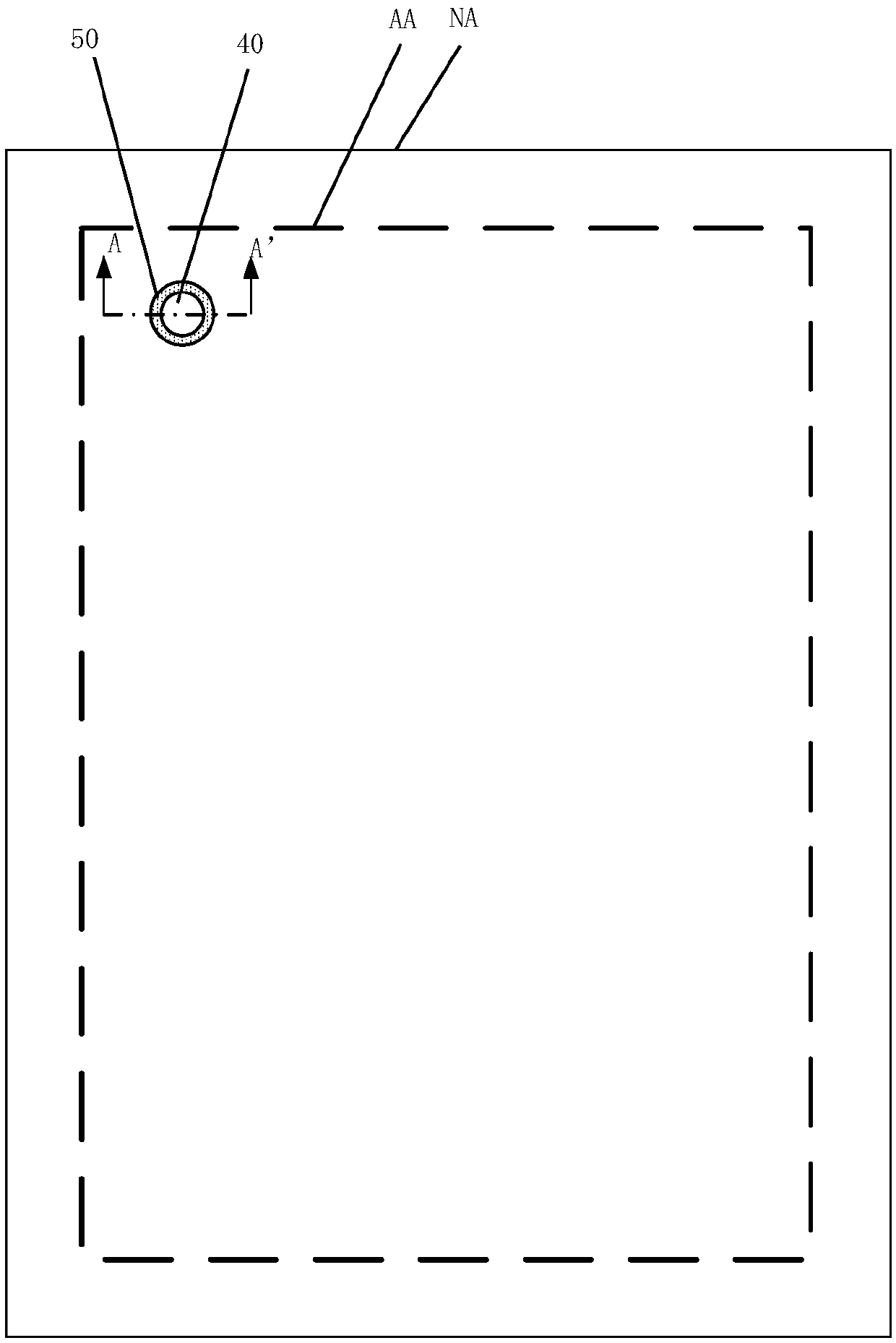
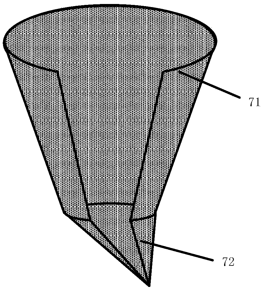
The invention discloses a display panel and the manufacturing method thereof, and a display device. The display panel has a display area and a non-display area surrounding the display area, which comprises relatively arranged array substrates, a color filter substrate, and a liquid crystal layer provided between the array substrates and the color filter substrate. A first via hole penetrates the array substrate and the liquid crystal layer. The display area is arranged around the first via hole. A colloidal frame structure is located between the first via hole and the display area. The vertical projection of the colloidal frame structure on the plane of the array substrates is a closed pattern, and the colloidal frame surrounds the vertical projection of the first via hole on the plane ofthe array substrates. A plurality of grooves are located on the side wall formed by the colloidal frame structure, and the grooves are formed by the side wall of the colloidal frame structure being recessed toward the display area. A plurality of reflective structures are provided in the grooves. The invention can effectively improve the performance of accessories such as cameras in a display terminal.

Description

technical field [0001] The present invention relates to the field of display technology, and more specifically, to a display panel, a manufacturing method thereof, and a display device. Background technique [0002] With the development of display panels, people are no longer only satisfied with conventional performance indicators such as large size and high definition of display panels, but also have more diverse requirements for display panels. A display device with a high screen-to-body ratio can bring a brand-new feeling and experience to users, and thus is favored by users. Currently, the display device on the market generally sets the camera in the non-display area, thereby increasing the area of ​​the non-display area, resulting in a decrease in the area of ​​the display area and a decrease in screen-to-body ratio, which is unfavorable for users to obtain a good visual experience. [0003] Therefore, in order to increase the screen-to-body ratio of the display device...

Claims


Application Information

Patent Timeline
Patent Type & Authority Applications(China)
IPC IPC(8): G02F1/1339G02F1/1335
CPCG02F1/133553G02F1/1339
Inventor 郑泽源余艳平凌安恺沈柏平
Owner XIAMEN TIANMA MICRO ELECTRONICS
Learn More