Collecting device and method for connecting state of heavy-current device

A state acquisition and equipment connection technology, applied in space navigation equipment, simulation devices of space navigation conditions, transportation and packaging, etc., can solve problems such as failure to detect errors in time, burning modules, and failure to detect connection errors in time.

Active Publication Date: 2019-04-02
权斌 +2
View PDF6 Cites 1 Cited by
  • Summary
  • Abstract
  • Description
  • Claims
  • Application Information

AI Technical Summary

Problems solved by technology

[0004] First, the application system composed of modules mounted on the installation board cannot detect connection errors in time with traditional methods, and the workload for detecting errors in complex systems is very large, which brings certain difficulties to the teacher's guidance
[0005] Second, because the traditional method is for students to connect according to the teaching materials, it is impossible to find errors in the connection in time. Serious errors will not only caus

Method used


Image

  • Collecting device and method for connecting state of heavy-current device
  • Collecting device and method for connecting state of heavy-current device
  • Collecting device and method for connecting state of heavy-current device

Examples


Embodiment 1

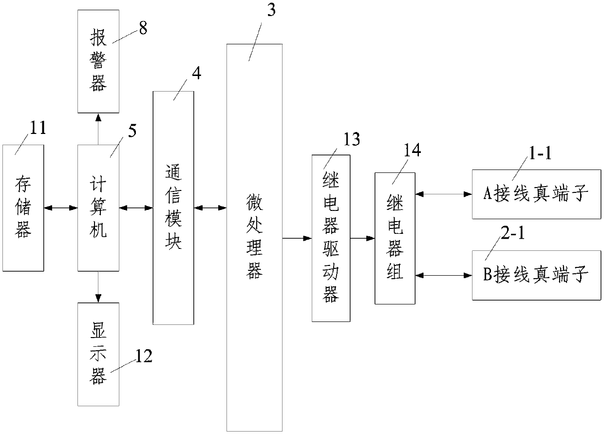
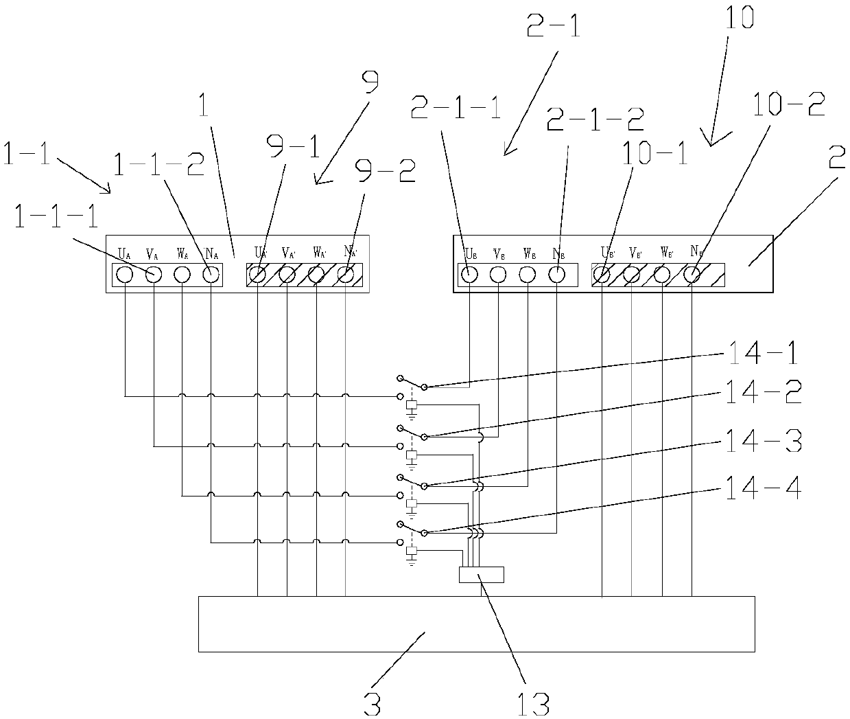
[0120] Such as figure 1 with figure 2 As shown, a device for collecting the connection status of high-voltage equipment includes A device 1 and B device 2 arranged on a training operation panel 2 and pseudo wiring terminals arranged on the front side of the training operation panel for trainees to train, and The real connection terminal arranged on the rear side of the training operation panel, and the terminal collection connection module used to collect the connection state of the pseudo connection terminal and used to truly connect the real connection terminal and the terminal collection connection module connected to the terminal collection connection module A computer monitoring module, the true wiring terminals include the A wiring true terminal 1-1 of the A device 1 and the B wiring true terminal 2-1 of the B device 2, and the pseudo wiring terminal includes the true terminal 1 connected to the A -1 corresponding to the A-wiring pseudo terminal 9 and the B-wiring pseudo...

Embodiment 2

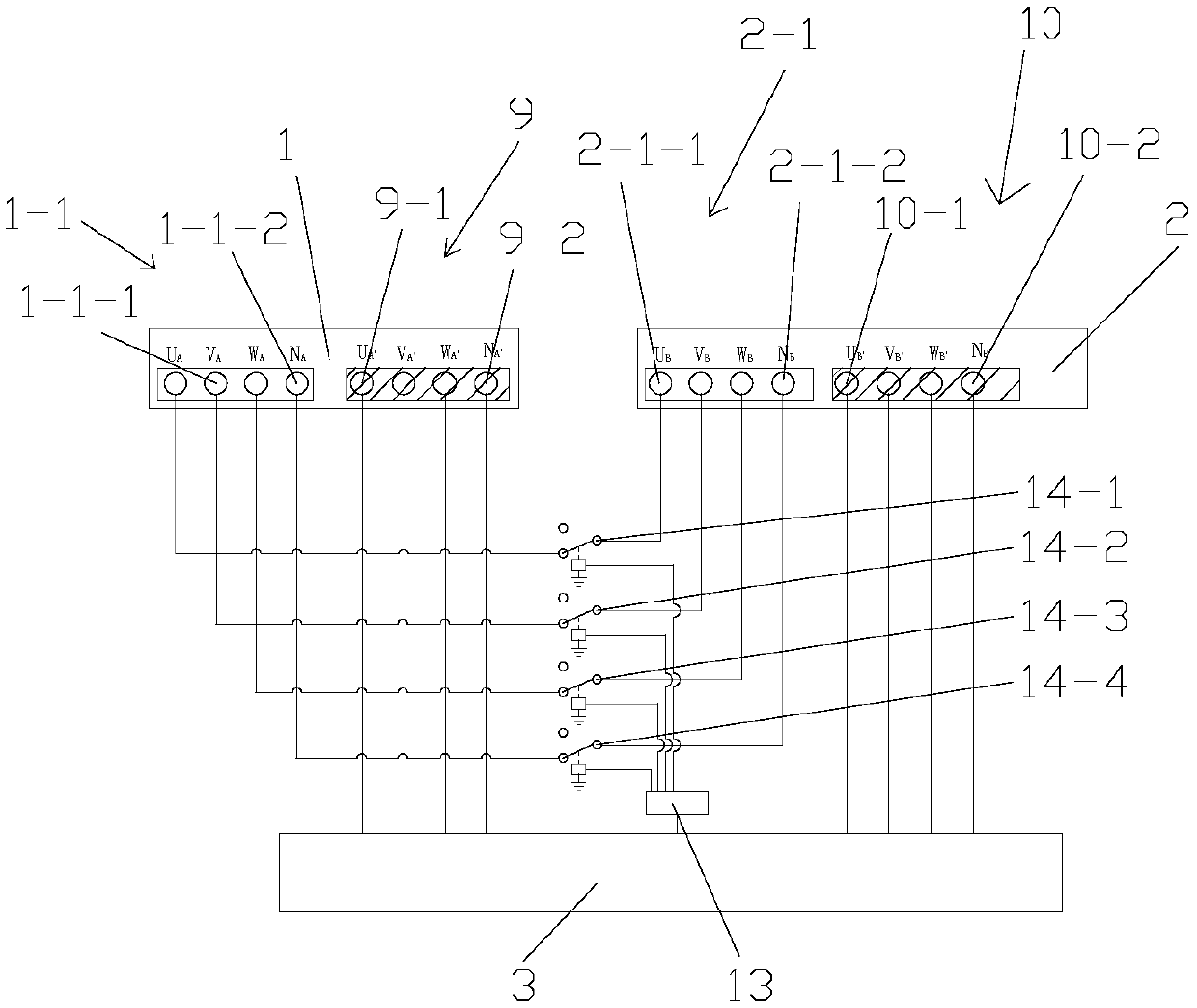
[0163] Such as image 3 As shown, in this embodiment, the difference from embodiment 1 is: the normally closed contact of the U-phase conductive relay 14-1 and the U-phase line A true terminal U A Connected, the normally open contact of the U-phase conductive relay 14-1 is suspended, and the normally closed contact of the V-phase conductive relay 14-2 is connected to the true terminal V of the V phase line A A Connected, the normally open contact of the V-phase conductive relay 14-2 is suspended, and the normally closed contact of the W-phase conductive relay 14-3 is connected to the true terminal W of the W phase line A A Connected, the normally open contact of the W-phase conductive relay 14-3 is suspended, and the normally closed contact of the neutral line conductive relay 14-4 is connected to the true terminal N of the neutral line A A Connected, the normally open contact of the neutral conductive relay 14-4 is suspended.

[0164] In this embodiment, it should be noted that whe...

Embodiment 3

[0171] Such as Figure 4 with Figure 5 As shown, in this embodiment, the difference from Embodiment 1 is that the relay group 14 includes a collection relay group for collecting the connection status of the A-wired pseudo terminal 9 and the B-wired pseudo terminal 10, and for controlling the A-wired true terminal 1-1 The conduction relay group 15 connected with the B wiring true terminal 2-1 and the relay AC power supply 16 for supplying power to the conduction relay group 15, and the collection relay group includes a connection state for collecting the A wiring pseudo terminal 9 The first phase line collection relay group 19 and the first zero line collection relay 17 as well as the second phase line collection relay group 20 and the second zero line collection relay 18 for collecting the connection status of the B wiring pseudo terminal 10, the first The phase-line collection relay group 19 includes a first U-phase collection relay 19-1, a first V-phase collection relay 19-2,...


PUM


Abstract

The invention discloses a collecting device for the connecting state of a heavy-current device, and also discloses a collecting method for the connecting state of an alternating-current heavy-currentdevice. The method comprises the following steps: 1, numbering wiring terminals of the alternating-current heavy-current device; 2, establishing a correct connecting database and a heavy current wrongconnecting database of the alternating-current heavy-current device; 3, collecting the connecting state of alternating-current heavy-current pseudo terminals; and 4, judging the connecting state of the alternating-current heavy current and displaying the connecting of the alternating-current heavy-current device. The invention further discloses a collecting device for the connecting state of a direct-current heavy-current device. A method comprises the following steps: 1, numbering wiring terminals of the direct-current heavy-current device; 2, establishing a correct connecting database and aheavy current wrong connecting database of the direct-current heavy-current device; 3, collecting the connecting state of direct-current heavy-current pseudo terminals; and 4, judging the connectingstate of the direct-current heavy current and displaying the connecting of the direct-current heavy-current device. With the devices and the methods, the connecting state of the heavy-current device in a practical training module can be accurately collected.

Description

Technical field [0001] The invention belongs to the technical field of the connection state of high-voltage equipment, and particularly relates to a device and method for collecting the connection state of high-voltage equipment. Background technique [0002] At present, domestic higher education, especially vocational education, has higher and higher requirements for engineering training, and the common electronic engineering training products on the market are application systems composed of modules connected to mounting boards. The training method for the training circuit board is to verify the correctness of the circuit or the function of a certain device through the provided training guide, but it cannot be verified for the wrong design. The training method for installing functional modules on the mounting board is to install under the guidance of the training guide. The correctness of the installation cannot be discovered in time, and the teacher's guidance is also very he...

Claims


Application Information

Patent Timeline
IPC IPC(8): G09B9/00G09B23/18
CPCG09B9/00G09B23/188
Inventor 权斌权溦徐红
Owner 权斌
Why Eureka
Try Eureka