Submersible motor

A technology for submersible motors and rotating shafts, which is applied in the direction of electrical components, electromechanical devices, electric components, etc., can solve the problems of reduced service life and impact on the service life of submersible motors, and achieve the effects of improving sealing effects, good sand control effects, and reducing possibilities

Inactive Publication Date: 2019-04-02
LORENTZ PUMP & MECHANICS BEIJING CO LTD
View PDF5 Cites 2 Cited by
  • Summary
  • Abstract
  • Description
  • Claims
  • Application Information

AI Technical Summary

Problems solved by technology

[0003] When the submersible electric pump transports liquid containing impurities such as gravel, it is necessary to protect the shaft end of the submersible motor to prevent impurities such as gravel in the liquid from entering the submersible motor, causing wear to the parts in the motor and reducing the service life
[0004] The current submersible motors mostly use sand throwing rings to prevent impurities such as gravel in the liquid from entering the motor. During the operation of the motor, due to the centrifugal effect of the sand throwing ring and the "positive pressure effect" in the cavity generated by the heat generated by the motor, this Gravel will not enter the inner cavity of the motor, but when the motor stops running, the gradual cooling of the motor cavity will form a "negative pressure effect". The service life of the motor is affected

Method used


Image

  • Submersible motor
  • Submersible motor
  • Submersible motor

Examples


Embodiment

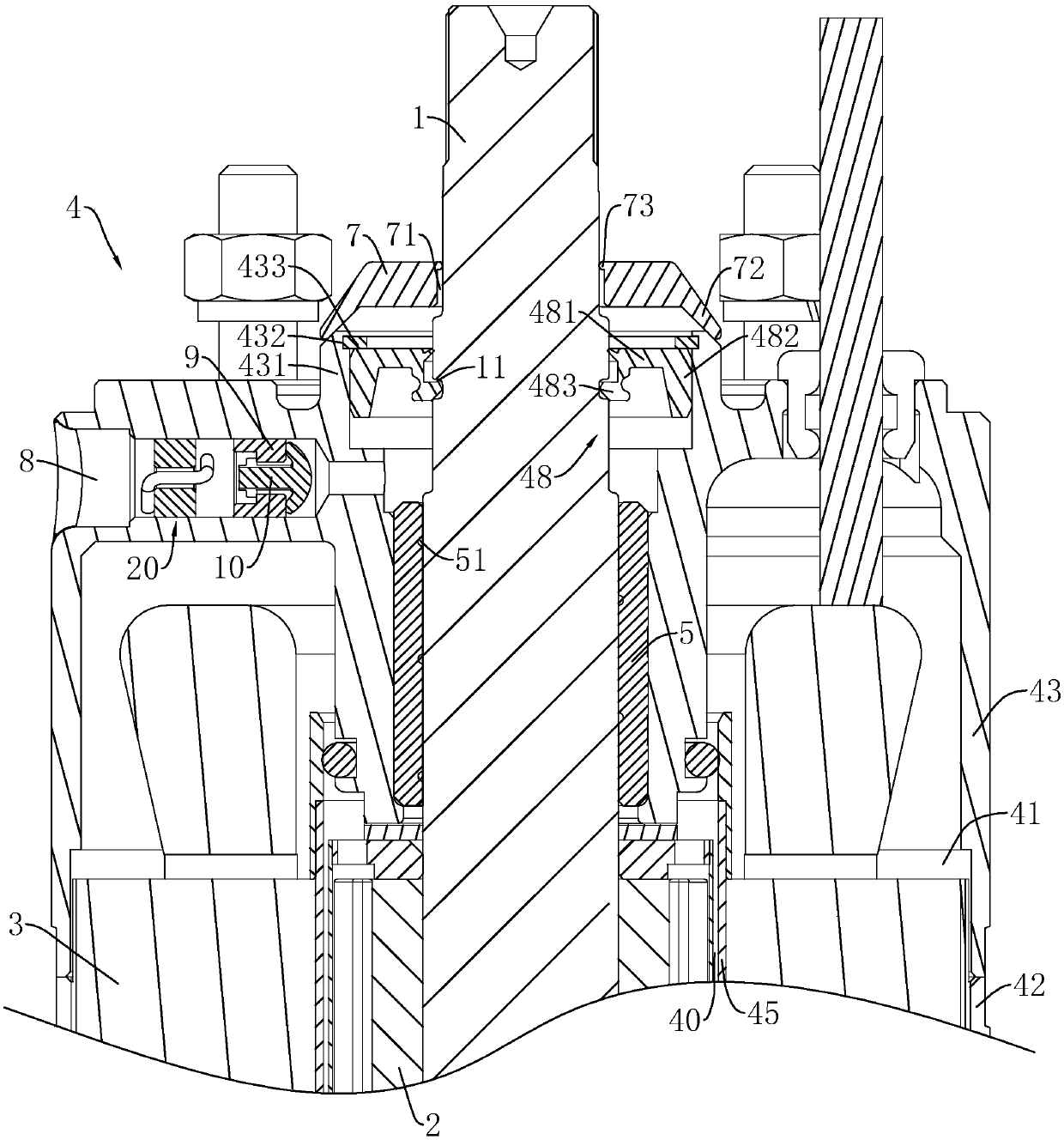
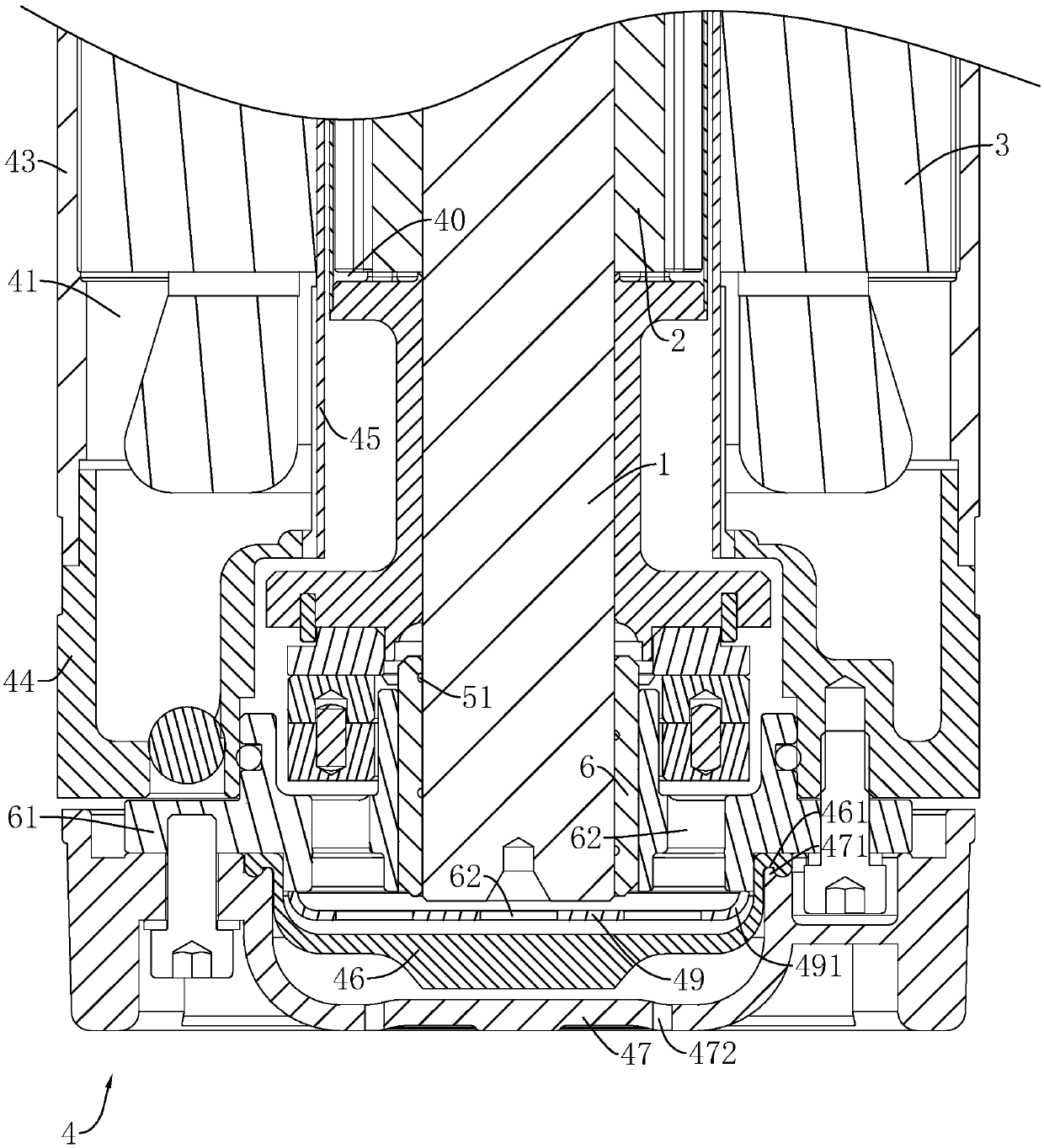
[0038] Embodiment: a kind of submersible motor, such as figure 1 , figure 2 As shown, it includes a rotating shaft 1, a rotor 2, a stator 3, and a housing assembly 4 having an inner cavity 40 and an outer cavity 41. The housing assembly 4 includes a barrel 42, an upper fixing seat 43, a lower fixing seat 44, a shielding sleeve 45, Diaphragm 46 and base 47 and other components.

[0039] The upper fixing seat 43 is fixed and sealingly connected with the upper end of the barrel 42 , and the lower fixing seat 44 is fixed and sealingly connected with the lower end of the barrel 42 . The shielding sleeve 45 is located in the machine barrel 42, and the upper and lower ends of the shielding sleeve 45 are respectively fixed and sealed with the upper fixing seat 43 and the lower fixing seat 44. The space between them is the outer cavity 41 . The stator 3 is located in the outer cavity 41 and fixedly connected with the barrel 42 , the rotating shaft 1 is located in the inner cavity 4...


PUM


Abstract

The invention discloses a submersible motor. According to the technical scheme, the submersible motor is characterized by comprising a rotating shaft, a rotor, a stator, and a shell assembly equippedwith an inner cavity and an outer cavity; the rotating shaft is located in the inner cavity, and one end of the rotating shaft penetrates out of the shell assembly; one end, penetrating out of the shell assembly, of the rotating shaft is in interference fit with a sand prevention cap; a support table vertically extends out of the shell assembly, and the sand prevention cap is buckled on the support table; a sealing part is arranged between the rotating shaft and the support table; the shell assembly is provided with a water supplementing hole for communicating the inner cavity with the outside, and a flow limiting assembly for balancing the internal pressure and the external pressure of the submersible motor is arranged in the water supplementing hole; and a filter part is arranged on oneside of the flow limiting assembly. According to the submersible motor, the gravel can be blocked outside the motor, the inner pressure and the outer pressure of the motor can be kept consistent, andthe usability and reliability of the whole motor are improved.

Description

technical field [0001] The invention relates to a submersible motor. Background technique [0002] Submersible electric pumps are widely used in various fields of industrial and agricultural production and daily life. Submersible electric motors are an important part of submersible electric pumps. They are mainly divided into dry type (the motor is completely sealed), semi-dry type (the stator of the motor is sealed, and the rotor is in the running in water), oil-filled (the motor is filled with oil to prevent moisture from invading the windings) and wet (the motor is filled with water, and both the stator and the rotor run in water). [0003] When the submersible electric pump transports liquid containing impurities such as gravel, it is necessary to protect the shaft end of the submersible motor to prevent impurities such as gravel in the liquid from entering the submersible motor, causing wear to the parts in the motor and reducing the service life. [0004] The current ...

Claims


Application Information

Patent Timeline
Patent Type & Authority Applications(China)
IPC IPC(8): H02K5/10H02K5/124H02K5/132H02K7/00H02K5/16
CPCH02K5/10H02K5/124H02K5/132H02K5/161H02K7/003
Inventor 本特·劳伦斯
Owner LORENTZ PUMP & MECHANICS BEIJING CO LTD
Why Eureka
Try Eureka